Spendor sp 100 owners manual

This is the 3 pages manual for spendor sp 100 owners manual.
Read or download the pdf for free. If you want to contribute, please mail your pdfs to info@audioservicemanuals.com.

Page: 1 / 3
left right
spendor sp 100 owners manual

Extracted text from spendor sp 100 owners manual (Ocr-read)


Page 1

Spendor SPlOO Specification

Low Frequency unit Spendor 300mm Bextrene

Mid Frequency unit Spendor 160mm Homopolymer Polypropylene
High Frequency unit 19mm Soft Dome

Crossover point 600Hz, 4kHz

Nominal Impedance 8 ohms

Frequency response tSdB 45Hz to 20kHz

Pair Matching Within 1dB

Power Handling 125 watts

Sensitivity 90dB/1 watt/1 metre

Maximum SPL 110dBA at 1 metre

Input connections Gold-plated 4mm terminals, Tri-wire option
Cabinet size (HXWXD) 700 x 370 x 430mm (27.5 x 14.5 x 17 in)
Weight 36kg (79lb)

Due to a puilcy of continual development Spendor Audio Systems Limrted reserves the right to make changes Without notice to these spemfitations.

Loudspeaker Positioning

Spendor SP100 loudspeakers are designed to be free-standing, in that there should be an air space between the cabinet
and large surface areas (walls and floor). The high frequency unit should be at about ear height for the normal listening
position. If mounted above or below it will be advantageous to tilt them to face the listener.

Where loudspeakers have to be placed near to the corners of a room, they should be positioned non-equidistant from the
side and rear walls. This reduces the effect of the phase differences between the reflections from the two walls and the
directly radiated sound. Most loudspeakers should never be placed tightly into a corner, for although this increases the
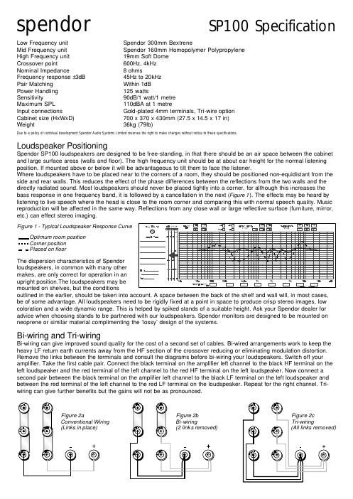
bass response in one frequency band, it is followed by a cancellation in the next (Figure 1). The effects may be heard by
listening to live speech where the head is close to the room corner and comparing this with normal speech quality. Music
reproduction will be affected in the same way. Reflections from any close wall or large reflective surface (furniture, mirror,
etc.) can effect stereo imaging.

=EI "El "nun. Elli!
W43 -Ei ' ' E Ei El

Figure 1- Typical Loudspeaker Response Curve -- < fit' g g -71- E El El

_ Optimum room position
- - - - Corner position
- - Placed on floor

The dispersion characteristics of Spendor
loudspeakers, in common with many other
makes, are only correct for operation in an
upright position.The loudspeakers may be
mounted on shelves, but the conditions
outlined in the earlier, should be taken into account. A space between the back of the shelf and wall will, in most cases,
be of some advantage. All loudspeakers need to be rigidly fixed at a point in space to produce crisp stereo images, low
coloration and a wide dynamic range. This is helped by spiked stands of a suitable height. Ask your Spendor dealer for
advice when choosing stands to be partnered with our loudspeakers. Spendor monitors are designed to be mounted on
neoprene or similar material complimenting the lossy design of the systems.

w- m- -

I- 2.: =_-. Ix 2, Ni m I
l:l l:l l:l l:l l:l l:l l:l_.._l:|

BI-WIrIng and TrI-WIrIng

Bi-wiring can give improved sound quality for the cost of a second set of cables. Bi-wired arrangements work to keep the
heavy LF return earth currents away from the HF section of the crossover reducing or eliminating modulation distortion.
Remove the links between the terminals and consult the diagrams before bi-wiring your loudspeakers. Switch off your
amplifier. Take the first cable pair. Connect the black terminal on the amplifier left channel to the black HF terminal on the
left loudspeaker and the red terminal of the left channel to the red HF terminal on the left loudspeaker. Now connect a
second pair between the black terminal on the amplifier left channel to the black LF terminal on the left loudspeaker and
between the red terminal of the left channel to the red LF terminal on the loudspeaker. Repeat for the right channel. Tri-
wiring can give further benefits but the gains will not be as pronounced.

o
Figure 2b Figure 2c

Bi- wiring Tri-wiring
(2 links removed) {All links removed)


Figure 2a
Conventional Wiring
(Links in place)