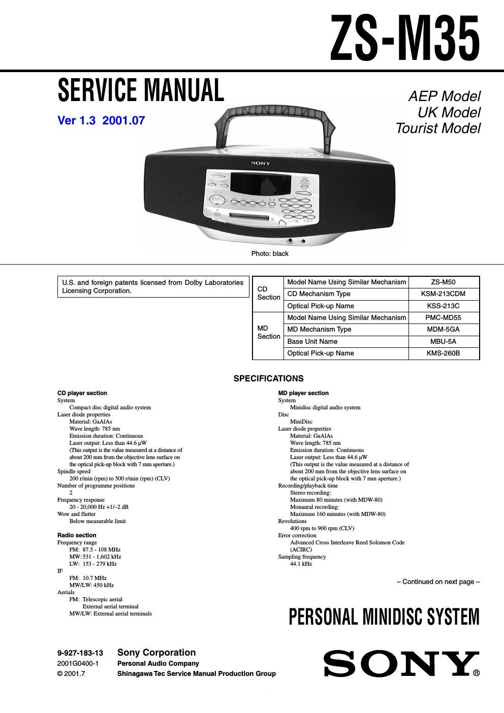
Sony zs m 35 ver 1 3

This is the 124 pages manual for sony zs m 35 ver 1 3.
Read or download the pdf for free. If you want to contribute, please mail your pdfs to info@audioservicemanuals.com.

Page: 1 / 124
left right
sony zs m 35 ver 1 3

Extracted text from sony zs m 35 ver 1 3 (Ocr-read)


Page 1

-“ 2 -“ Coding Adaptive TRansform Acoustic Coding (ATRAC) Modulation system EFM (Eight-to-Fourteen Modulation) Number of programme positions 2 stereo programme positions Frequency response 20 - 20,000 Hz +1/-“2 dB Signal-to-noise ratio Over 80 dB (during playback) Wow and flutter Below measurable limit General Speaker Full-range: 8 cm (3 in.) dia.,4 ohms, cone type (2) Inputs LINE IN (stereo minijack):Sensitivity 436 mV/ 870 mV Outputs Headphones jack (stereo minijack) (1): For 32 ohms impedance headphones Maximum power output 5 W + 5 W Power requirements For personal minidisc system: 230 V AC, 50 Hz For back-up memory: 4.5 V DC, 3 R6 (size AA) batteries For remote control: 3 V DC, 2 R6 (size AA) batteries Power consumption 24 W Dimensions (incl.projecting parts) approx. 498.5 Ă— 173.5 Ă— 227 mm (w/h/d) (19 3/4 Ă— 6 7/8 Ă— 11 inches) Mass approx. 5.2 kg (11 lb. 7 oz) Supplied accessories Mains lead (1) Remote control (RMT-CM35AD) (1) MW/LW loop aerial (1) Design and specifications are subject to change without notice.

Page 2

-“ 3 -“ 1. SERVICING NOTES 1-1. Notes on Handling the Optical Pick-up Block or Base Unit .. 4 1-2. Notes on Laser Diode Emission Check ............................... 4 1-3. Notes on Chip Component Replacement ............................ 4 1-4. Flexible Circuit Board Repairing ........................................ 4 1-5. Chuck Plate Jig on Repairing .............................................. 4 1-6. Demonstration ..................................................................... 4 1-7. Checking the Laser Diode and Focus Search Operation ..... 4 1-8. Jig for Checking BD Board Waveform ............................... 5 1-9. Checks Prior to Parts Replacement and Adjustments ......... 6 1-10. Change of Pulley ................................................................. 6 2. GENERAL Playing a CD ....................................................................... 7 Recording a whole CD ........................................................ 7 Playing an MD ..................................................................... 8 Listening to the radio ........................................................... 8 3. DISASSEMBLY 3-1. Cabinet (Rear) Assy ............................................................ 9 3-2. Power Board ........................................................................ 9 3-3. Cabinet (Upper) Assy ........................................................ 10 3-4. MD Block Assy ................................................................. 10 3-5. Tuner Board ....................................................................... 11 3-6. Jack Board ......................................................................... 11 3-7. LED Board ........................................................................ 12 3-8. Key Board ......................................................................... 12 3-9. Top Board .......................................................................... 13 3-10. FL Board ........................................................................... 13 3-11. Main board ........................................................................ 14 3-12. CD Board .......................................................................... 14 3-13. CD Mechanism Block ....................................................... 15 3-14. DG Board .......................................................................... 15 3-15. Plate (Front), Shield .......................................................... 16 3-16. MD Mechanism Block-1 (MDM-5GA) ............................ 16 3-17. MD Mechanism Block-2 (Slider (Cam) Assy) ................. 17 3-18. MD Mechanism Block-3 (BD Board) ............................... 18 3-19. MD Mechanism Black-4 (SW Board) ............................... 18 4. TEST MODE 4-1. MD section ........................................................................ 19 5. ELECTRICAL ADJUSTMENTS 5-1. Tuner section ..................................................................... 24 5-2. MD section ........................................................................ 26 5-3. CD section ......................................................................... 33 TABLE OF CONTENTS 6. DIAGRAMS 6-1. IC Pin Function Descriptions ............................................ 35 6-2. Circuit Boards Location .................................................... 44 6-3. Block Diagram -“Tuner Section-“ ....................................... 45 6-4. Block Diagram -“MD Section-“ .......................................... 48 6-5. Block Diagram -“CD Section-“ ........................................... 51 6-6. Block Diagram -“Audio Section-“ ...................................... 53 6-7. Schematic Diagram -“CD Section (1/2)-“ ........................... 55 6-8. Schematic Diagram -“CD Section (2/2)-“ ........................... 57 6-9. Printed Wiring Boards -“CD Section-“ ............................... 59 6-10. Printed Wiring Boards -“Tuner Section-“ ........................... 61 6-11. Schematic Diagrams -“Tuner Section-“ .............................. 63 6-12. Printed Wiring Boards -“BD Section-“ ............................... 65 6-13. Schematic Diagram -“BD Section (1/2)-“ ........................... 67 6-14. Schematic Diagrams -“BD Section (2/2)-“ ......................... 69 6-15. Schematic Diagram -“DG Section-“ ................................... 71 6-16. Schematic Diagram -“DG Section-“ ................................... 73 6-17. Printed Wiring Board -“DG Section-“ ................................. 75 6-18. Printed Wiring Board -“Main Section-“ .............................. 77 6-19. Schematic Diagram -“Main Section (1/3)-“ ........................ 79 6-20. Schematic Diagram -“Main Section (2/3)-“ ........................ 81 6-21. Schematic Diagram -“Main Section (3/3)-“ ........................ 83 6-22. Printed Wiring Boards -“Panel Section-“ ............................ 85 6-23. Schematic Diagrams -“Panel Section-“ ............................... 87 6-24. Printed Wiring Boards -“Switch Section-“ .......................... 89 6-25. Schematic Diagrams -“Switch Section-“ ............................ 91 6-26. Printed Wiring Boards -“Power Supply Section-“ .............. 93 6-27. Schematic Diagrams -“Power Supply Section-“ ................. 95 6-28. IC Block Diagrams ............................................................ 97 7. EXPLODED VIEWS 7-1. Cabinet (Rear) Section .................................................... 103 7-2. Cabinet (Front) Section ................................................... 104 7-3. Cabinet (Upper) Section .................................................. 105 7-4. MD Block Section ........................................................... 106 7-5. MD Mechanism Section (MDM-5GA) .......................... 107 7-6. MD Base unit Section (MBU-5A) ................................. 108 7-7. Optical Pick-up Section (KSM-213CDM) ...................... 109 8. ELECTRICAL PARTS LIST .................................... 110