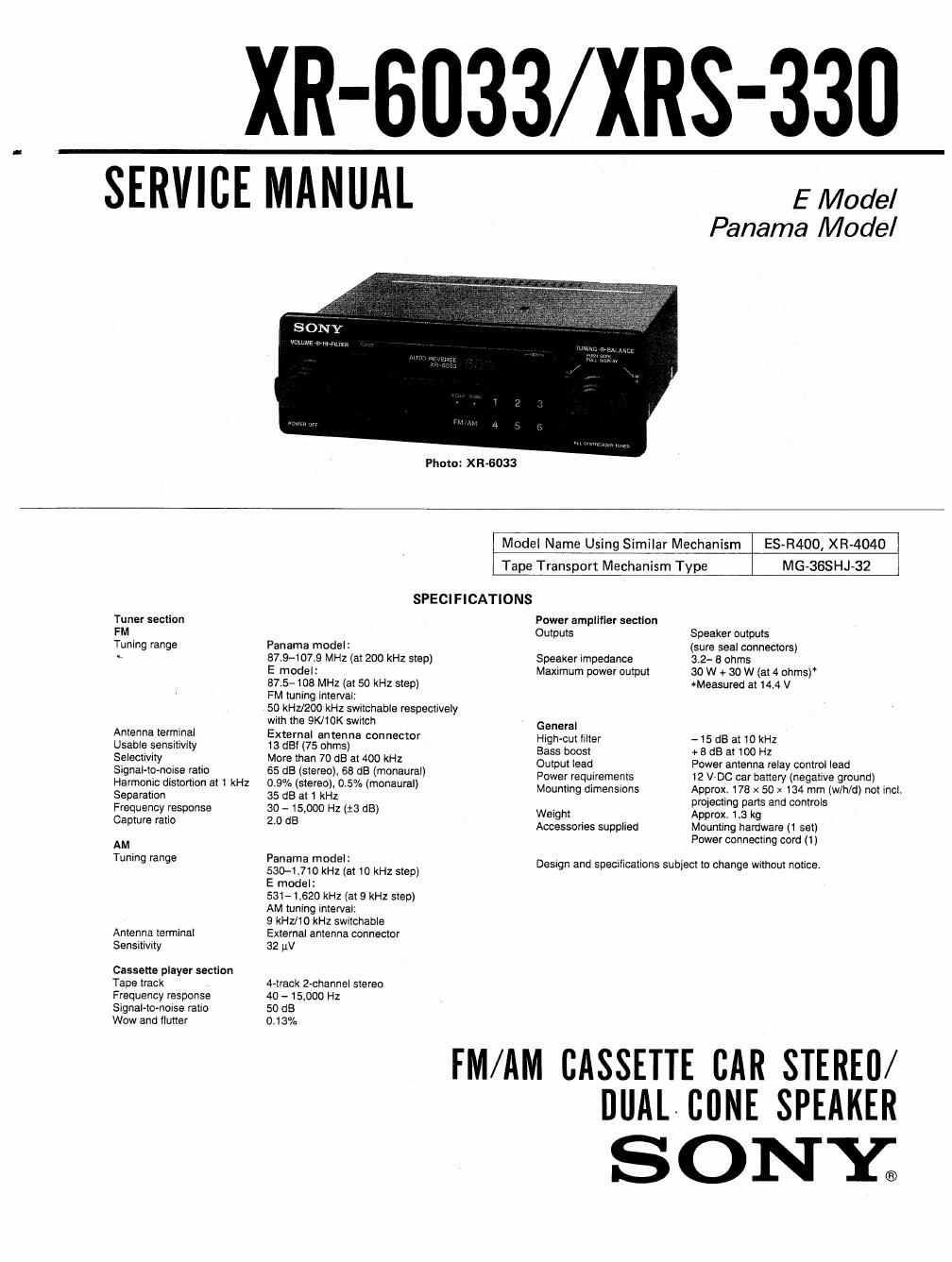
Sony xrs 330 service manual

This is the 24 pages manual for sony xrs 330 service manual.
Read or download the pdf for free. If you want to contribute, please mail your pdfs to info@audioservicemanuals.com.

Page: 1 / 24
left right
sony xrs 330 service manual

Extracted text from sony xrs 330 service manual (Ocr-read)


Page 2

XR-6033/XRS-330

Tuner section

-SSIR (Sony Super Interference Rejection) PLL
Synthesizer tuner.

-The quartz-locked digital synthesizer system
enables easy and accurate tuning.

- Up to 12 FM and 6 AM stations can be preset,

Cassette deck section
The auto-reverse function changes the tape
direction automatically.

Power amplifier section

- Maximum power output of 30 watts per
channel.

-The Hl-FlLTER (high-cut filter) eliminates the
frequency noise and delivers clear sound.

General
The quartz controlled digital clock

TABLE OF CONTENTS

Section Title Page
Specifications ................. . . 1
Features ................................. 2
SECTION I. GENERAL

Location and Function of Controls ----- 3

Installation ------ 4

Connections . . . . ........................ 5
SECTION 2. DISASSEMBLY ---------------- 6
SECTION 3. ADJUSTMENTS

3-1. Mechanical Adjustment ------------- 7

3-2. Electrical Adjustments ~ 7

SECTION 4. DIAGRAMS
4-1. Block Diagram .................... 10


4-2. Semiconductor Lead Layouts . 13
4-3. Printed Wiring Boards ~~ - 13
4-4. Schematic Diagram ---------------- 17

45. FEl FM Front End Schematic
SERVICING NOTE Diagram .......................... 20
4-5, 1c Block Diagram ----------------- 21

Flexible Circuit Board Repairing SECTION 5_ EXPLODED VIEWS

0 Keep the temperature of the soldering iron around 51' Chassis Assembly-l """""""" 22
270°C during repairing. 5-2. Chassis Assembly-2 ------------- 23
0 Do not touch the soldering iron on the same con- 5-3. MD Assembly-l (MG~36$HJ-32I ------ 24
cluster of the circuit board (within 3 times). 5-4. MD Assembly-2 (MG-SGSHJ-32) ----- 25

O Be careful not to apply force on the conductor

when soldering or unsoldering. SECTION 6. ELECTRICAL PARTS LIST - - r 26

Hardware List ......................... 31
Notes on chip component replacement
0 Never reuse a disconnected chip component.

0 Notice that the minus side of a tantalum capacitor
may be damaged by heat.