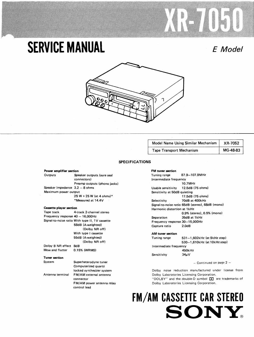
Sony xr 7050 service manual

This is the 23 pages manual for sony xr 7050 service manual.
Read or download the pdf for free. If you want to contribute, please mail your pdfs to info@audioservicemanuals.com.

Page: 1 / 23
left right
sony xr 7050 service manual

Extracted text from sony xr 7050 service manual (Ocr-read)


Page 2

R-7050

General
Tone controls Bass tSdB at IOOHZ

Treble tsdB at 10kHz

Loudness +6d3 at 100Hz
+6dB at 10kH1

Output lead Power antenna relay control
Ieed

Power requirements 12V DC ear battery (negative
ground)

Dimensions Approx. 178 x 50 x 160mm

(w/h/d)

(7/5x 2 x 65/. inches)
not incl. projecting parts and
controls

Mounting dimensions
Approx. 182 x 53 x 145mm
(w/h/d)
I7/.x 2/; x 5%
inches)
not incl. projecting parts and
controls
Weight Approx. 1.3kg (2 lb 14 oz)
Accessories supplied
Mounting hardware (1 set)
Fuses (1 set)
FEATURES
Tuner section
e Memory preset tuning function allows you to store
6 stations for each band in memory.
0 Preolse tuning is possible with the digital
synthesizer system.

We deck section

e Auto-reverse function to listen to both sides of a
cassette repeatedly.

eThe Dolby B NR system reduces tape hiss noise
during playback.

eAutom-tic Music Sensor (AMS) to locate the
beginning of a selection during playback.

General

0 Direct function system allows you to listen to the
program source selected last directly.

I You can control the balance of the front speakers
and the rear speakers in e Moeaker system with
an additional amplifier as well as with the built-in
amplifier (Multi-fader system).

eAuto Ioudnes circuit to reinforce the bass and
treble automatically when listening at a low
volume.

OMaxllnunI power output of 25 W + 25 W.

TABLE OF CONTENTS

Section Title Page
Specifications ................................ 1
Features ................................... 2
SECTION 1. GENERAL

l-l . Location and Function of Controls. .2

1-2. Connections ......................... 3
SECTION 2. MICROCOMPUTER SPECIFICATION

(11PD1708AG-765-00) ................ 5

SECTION 3. MECHANICAL ADJUSTMENT .......... 6
SECTION 4. ELECTRICAL ADJUSTMENT .......... 6
SECTION 5. DIAGRAMS

5-1. Semiconductors Lead Layout ............ ll

5-2. Printed Wiring Boards .................. 12

5-3. Schematic Diagram . . . . . . . . . 15

5-4. IC Block Diagram .................... 19
SECTION 6. EXPLODED VIEWS ................ 21
SECTION 7. ELECTRICAL PARTS LIST ........... 26

(r. in o .i o

M. SCAN (memory scan)!
A. MEM (aulomalic memory) button

SECTION 1

: (eject) button

Display window-fl

GENERAL
1-1. LOCATION AND FUNCTION OF CONTROLS

ficasefle insertion door

DIFI (tape Ilansnflrl dilecliorlll»l«
(last winding) bullons

FADEFl SELECT swllch __-..->] m


FADEFI control

LOCAL button
at
D M0 0
H N (monauraiibution
"5.... . . 3 S MAN (manuali +I- buttons
q) D 40 50 60 Bin +

VOL (Volume) control [PUSH POWER -J

swllch/F'ULL BAL (balance) control

LOUD button

%--SEEK +l- buttons
Preset number buttons

%-BAND bullon

BASS contra

DCHDOlby nOIse reduction) button

AMS (Automatic Music Sensor)
button

THEBLE control

0 a-.- it-.n-..---. . 0 .- n-----.n-nt- Hm-a---..-..-.i-n-.~.o