Sony xmsd 46 x owners manual

This is the 2 pages manual for sony xmsd 46 x owners manual.
Read or download the pdf for free. If you want to contribute, please mail your pdfs to info@audioservicemanuals.com.

Page: 1 / 2
left right
sony xmsd 46 x owners manual

Extracted text from sony xmsd 46 x owners manual (Ocr-read)


Page 1

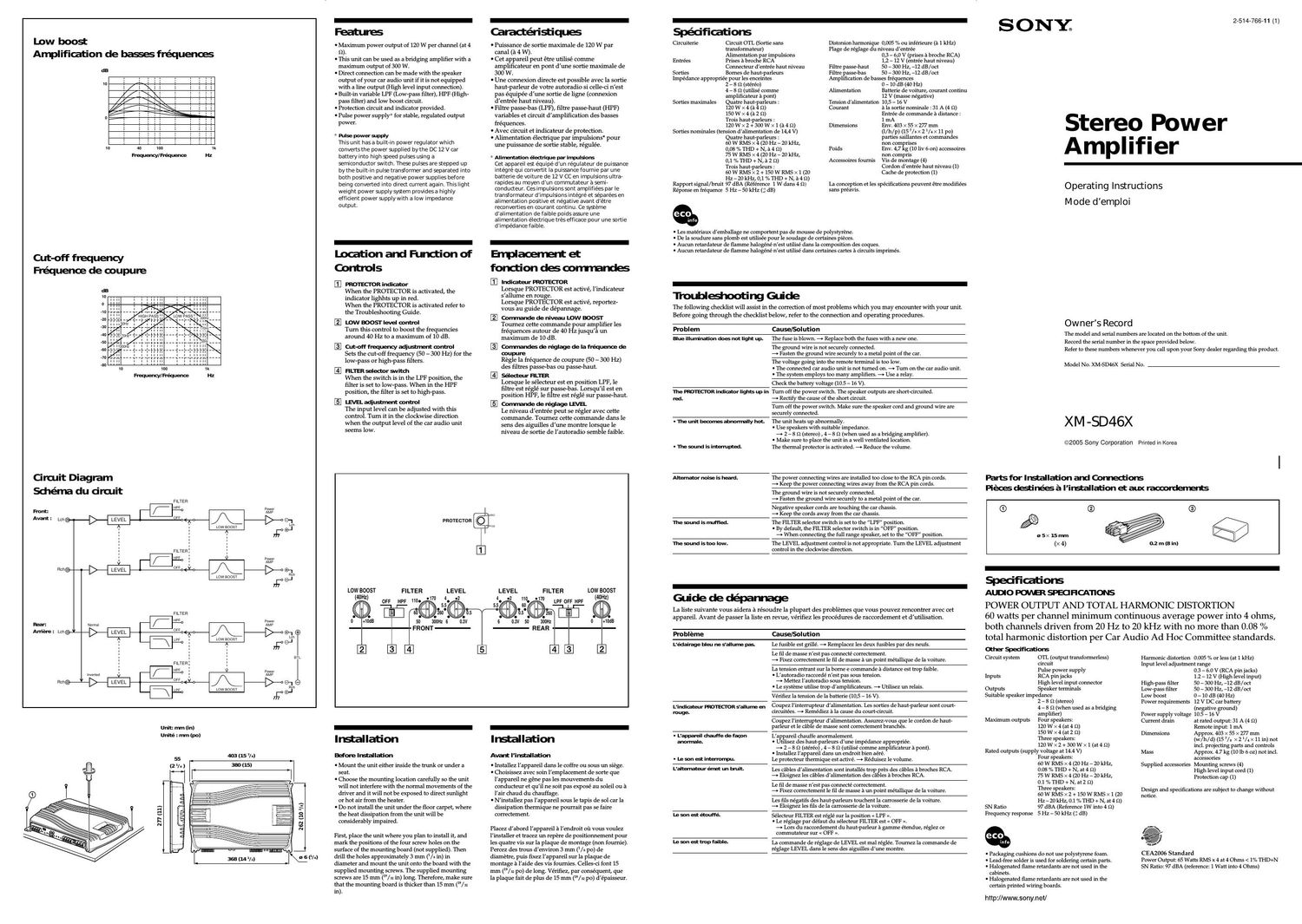
Low boost

Amplification de basses fréquenos

dB

10

Cut-off frequency
Fréquenoe de ooupure

Circuit Diagram
Schéma du circuit
FILTER

W

Front:

A

FILTER

Avant = Lch©- LEVEL 0 (To A
. LOW aoosr
LEVEL

Rch@- LEVEL

LFF Low BOOST

ave
Reno 0 <-V-c A {>-0®-j
towsoosr 63w
FILTER
are. P
men / iiié
Arnere: Lch© LEVEL We [>-oo-j
Len
use LowBoosT
i n ' = A #64
i : 1 an
: FILTER: 1
- we : . a
- / j irié
-l>-l:l so A

-
Features

I Maximum power output of 120 W per channel (at 4
52).

I This unit can be used as a bridging amplifier with a
maximum output of 300 W.

I Direct connection can be made with the speaker
output of your car audio unit if it is not equipped
with a line output (High level input connection).

I Built-in Variable LIF (Low-pass filter), HIF (High-
pass filter) and low boost circuit.

I Protection circuit and indicator provided.

I Pulse power supply* for stable, regulated output
power.

* Pulse power supply
This unit hasa built-in power regulator which
converts the power supplied by the DC 12 V Gr
battery into high speed pulses using a
semiconductor switch. These pulses are stepped up
by the built»in pulse transformer and separated into
both positive and negative power supplies before
being converted into direct current again. This light
weight power supply system provides a highly
efficient power supply With a low impedance
output.

-
Location and Function of
Controls

E] PROTECIOR indiator
When the PROTECTOR is activated, the
indicator lighhts up in red.
When the PROTECTOR is activated refer to
the Troubleshooting Guide.

Low BOOST level control
Turn this control to boost the frequencies
around 40 Hz to a maximum of 10 dB.

Cut-off frequency adjusment control
Sets the cutoff frequency (50 7 300 Hz) for the
loWspass or highspass filters.

E] FILTER selector swioch
When the switch is in the LPF position, the
filter 5 set to low5pa . When in the HPF
position, the filter i t to highspass.

E] LEVEL adjustment control
The input level can be adjusted with this
control. Turn it in the clockwise direction
when the output level of the car audio unit

-
I . .

Caractlensthues

I Puissance de sortie maximale de 120 W par
canal (a 4 W).

I Cet appareil peut étre utilisé comme
amplificateur en pont d'une sortie maximale de
300 W.

I Une connexion directe est possible avec la sortie
hautsparleur de votre autoradio si cellesci nest
pas équipée dune sortie de ligne (connexion
d'entTe'e haut niveau).

I Filtre passesbas (LPF), filtre passeshaut (HPF)
variables et circuit d'amplification des basses
fréquences.

I Avec circuit et indicateur de protection.

I Alimentation e'lectrique par impulsions" pour
une puissance de sortie stable, régulée.

* Alinerttau'on électrique par irrrpuls'ons
Cet appareil est équlpe d'un régulateur de pui$ance
intégré qui convertit ia puifince fournie par une
batterie de Volture de 12 V CC en impulsions ultra-
rapides au moyen d'un commutateur a semi-
conducteur. Ces impuislons sont amplifiees par le
transformateur d'impulstons integre et séparées en
alimentatlon positive et negative aVant d'étre
reconvertles en courarlt continu. Ce systéme
d'alimentation de faible polds asure llne
alimentation électrique trés efficace pour une sortie
d'impedance faible.

-
Errplaoement et
fonction d6 oorrrrandes

El lndiateur PROTECTOR
Lorsque PROTECTOR est activé, l'indicateur
s'allume en rouge.

Lorsque PROTECTOR est activé, reporter
vous au guide de depannage.

Comande de niveau Low Boosr
Tournez cette commande pour amplifier les
fre'quences autour de 40 Hz jusqu'a un
maximum de 10 dB.

Commaderéglagedelafréquaicede
coupure
Regle la fre'quence de coupure (50 7 300 Hz)
des filtres passe-bas ou passeshaut.

selecteur HLTER
Lorsque le se'lecteur est en position LPF, le
filtre est re'glé sur passesbasr Lorsqu'il est en
position HPF, le filtre est re'gle' sur passe-haut.

El Commie de reglage LEVEL
Le niveau d'entTe'e peut se régler avec cette
commande. Tournez cette commande dans le
sens des aiguilles dune montre lorsque le

seems 10W: niveau de sortie de lautoradio semble faible.
PROTECTOR
LOW BOOST FILTER LEVEL LEVEL FILTER LOW BOOST
(MHZ) OFF HPF no. 0170 .2 4. .2 no. 0170 (40HZ)

4.
.5
o

5
i a
50 250
o o o o 0
0 thB 50 (mom a
FRONT

LPF OFF HPF

9 E
1.5 . 260 [i .

o .
0.3V 51 (mill 0 +10liB

REAR
o b

Unit: "In (in)
Unité : mn (p0)

55

403 (15 7/5)

277 (11)

.ii

(2 IA) 330 (15)

262 (10 3h)

El

kc gar
355mm) \EV"

Installation

Before Irmllation

I Mount the unit either inside the trunk or under a
seat.

I Choose the mounting location carefully so the unit
will not interfere with the normal movements of the
driver and it will not be exposed to direct sunlight
or hot air from the heater.

I Do not install the unit under the floor carpet, where
the heat dissipation from the unit will be
considerably impaired.

First, place the unit where you plan to install it, and
mark the positions of the four screw holes on the
surface of the mounting board (not supplied). Then
drill the holes approximately 3 m (/t in) in
diameter and mount the unit onto the board with the
supplied mounting screws. The supplied mounting
screws are 15 mm (9/ :1 in) long. Therefore, make sure
that the mounting board is thicker than 15 mm (/32
in).

Installation

Am I'irstallation

I lnstallez lappareil dans le coffre ou sous un siége.

I Choir sez avec soin lemplacement de sorte que
lappareil ne gene pas les mouvements du
conducteur et quil ne soit pas expose au soleil on a
lair chaud du chauffage.

I N installez pas lappareil sous le tapis de sol car la
dissipation thermique ne pourrait pas se faire
correctement.

llacez dabord lappareil a lendroit oil vous voulez
linstaller et tracez un repere de positionnement pour
les quatre vis sur la plaque de montage (non fournie).
lercez des tTous denviron 3 mm (Vt po) de
diametre, puis fixez l/appareil sur la plaque de
montage a l/aide des Vis fournies. Celles-ci font 15
mm (/52 po) de long. Vérifiez, par consequent, que
la plaque fait de plus de 15 mm (/11 po) depaisseur.

Spécifications

Circuiterie Circuit OTL (Sortie sans

transformateur)

Alimentation par impulsions
Entrees Prises a brochc RCA

Connecteur dcntrée haut niveau
Sorties Bomes de haut-parleurs

Impedance appropriee pour les enceintes
2 - s 9 (stereo)
4 _ 8 Q (utilise comme
amplificateur a pnnt)
Sorties maximales Quatre haut-parlours :
120 w x 4 (a 4 Q)
151)Wx4(a2t2)
Trois haut-parleurs :
120WX2+300W><1(54Q)
Sorties nonunales (tension dalimentation de 14,4 V)
Quatre haut-parleurs :
60 w RMS x 4 (20 Hz - 20 kHz,
0,08%THD+N,a4Q)
75WRMS><4(2UHzAzOld-lz,
0,1 %THD+N,aZQ)
Trois haut-parleurs :
60WRMS><2+1SUWRMS><1 (20
Hz-ZOkHz,0,1 %THD+N,a4o)
Rapport signal/bruit 97 dBA (Reierence 1 w dans 4 Q)
Reponse en fréquence 5 Hz - 50 kHz ('5 dB)

Distorsion harmonique 0,005 % ou inférieure (a 1 kHz)
Plage de reglage du niveau d'entree
0,3 - 6,0 V (prises a broche RCA)
1,2 - 12 V (entree haut niveau)
Filtre passe-haut 50 - 300 Hz, -12 dB/oct
Filtre passe-bas 50 - 300 Hz, -12 dB/oct
Amplification de basses fréquences
0 - 10 dB (40 Hz)
Batterie de voiturc, courant continu
12 V (masse negative)
Tension dalimentation 105 - 16 V

Alimentation

Courant a la sortie nominale : 31 A (4 a)
Entree de commande a distance :
1 mA

Dimensions Env. 403 x 55 x 277 mm

(l/h/p) (15 7/t x 21/. x 11 po)
parties saillantes et commandes
non comprises

Poids Env. 4,7 kg (10 Liv 6 on) accessoires
non compris

Accessoires fournis Vis de montage (4)

Cordon dentrée haut niveau (1)
Cache de protection (1)

La conception et les specifications peuvent etre moditiees
sans preavis.

- Les matériaux demballage ne comportent pas de mousse de polystyrene.
- Dela soudure sans plomb est utilisee pour le soudage de certaines pieces.
- Aucun retardateur de flamme halngéné nest utilisé dans la composition des coques.

I Aucun retardateur dc f1amme halogéné nest utilise dans certaines cartes a circuits imprimés.

Troublediootlng Gude
The following checklist will assist in the correction of most problems which you may encounter with your unit.
Before going through the checklist below, refer to the connection and operating procedures.

Problem

Cause/Solution

Hue illurrination dos not light up.

The fuse is blown, 4t Replace both the fuses with a new one.

The ground wire is not securely connected.
a Fasten the ground wire securely to a metal point of the car.

The voltage going into the remote terminal is too low.
. The connected car audio unit is not turned on, a Turn on the car audio unit.
- The system employs too many amplifiers. A Use a relay.

Check the battery voltage (10.5 - 16 V).

The PaorEcron indiator lights up in

red.

Turn off the power switch. The speaker outputs are short-circuitcd.
a Roctity the cause of the short circuit.

Turn off the power switch. Make sure the speaker cord and ground wire are
securely connected.

I The unit bemrrs abnnrrrally hat.

- The sound is interrupted.

The unit heats up abnormally.
- Use speakers with suitable impedance.

a 2 - s 9 (stereo) , 4 - s 9 (when used as a bridging amplifier).
. Make sure to place the unit in a well ventilated location.
The thermal protector is activated. a Reduce the volume.

Altanatnr noise is heard.

The power connecting wires are installed too close to the RCA pin cords.
a Keep the power connecting wires away from the RCA pin cords.

The ground wire is not securely connected.
a Fasten the ground wire securely to a metal point of the car.

Negative speaker cords are touching the car chassis.
a Keep the cords away irorn the car chassis.

The mum! is muffled.

The FILTER selector switch is set to the LPF position.
- By default, the FILTER selector switch is in "OFF position.
a When connecting the full range speaker, set to the "OFF" position.

The mum! istno low.

The LEVEL adjustment control is not appropriate. Turn the LEVEL adjustment
control in the clockwise direction.

SONYs

2-514-766-11 (1)

Stereo Power
Amplifier

Operating Instructions

Mode d'emploi

Owner's Record

The model and serial numbers are located on the bottom of the unit.

Record the serial number in the space provided below.
Refer to these numbers whenever you call upon your Sony dealer regarding this product,

Model No. XM-SD46X Serial No.

XM -SD46X

@2005 Sony Corporation Printed in Korea

Hrtsfor Irstallation and Cornectiors
Fiéos datinéa é I'irlstallation et aux raooolderrats

® o
it

..\\\\\\

65X 15m"
(x4)

%

0.2 m (8 in)

. I
Glllde de depanrage

La liste suivante vous aidera a re'soudre la plupart des problemes que vous pouvez rencontrer avec cet
appareil. Avant de passer la liste en revue, vérifiez les procedures de raccordement et d'utilisation.

Probléme

Cause/Solution

L'édairage bleu ne sallurne pas

Le fusible est grille. 4t Remplacez les deux fusibles par des neufs.

Le fil de masse nest pas connecte correctement.
a Fixez correctement le fil de masse a un point métallique de la voiture.

La tension entrant sur la borne e commande a distance est trop faible.
- Lautoradin raccorde n'est pas sous tension.

4r Mettez lautoiadio sous tension.
- Le systeme utilise trop damplificateurs, 4. Utilisez un relais.

Vérifiez la tension de la batterie (10,5 - 16 V).

L'indiateur WTECI'OR S'allune 31
range.

Coupez lintcrrupteur dalimentation. Les sorties de haut-parleur sont court-
circuitées. 4r Remédiez a la cause (in court-circuit.

Coupez lintcrrupteur dalimentation. Assurez-vous cjue le cordon de haut-
parleur et le cable de masse sont correctement branches.

- L'appareil dlauffe de fag)"
anorrnale.

- Lesnn atirmerrompu.

Lappareil chauffe anormalement.
- Utilisez des haut-parleurs dune impedance appropriee.

a 2 e s 9 (stereo) , 4 - 8 r2 (utilise comme ampliiicateur a pont),
- Installez lappareil dans un endmit bien aere.
Le protecteur thermique est active. 4r Reduisez le volume.

L'alternateur érrlat un bruit.

Les cables dalimentation sont installés trop prés des cables :1 broches RCA.
4r Eloignez les cables dalimentation des cables a broches RCA.

Le fil de masse nest pas connecte correctement.
a Fixez correctement le fil de masse a un point metallique de la voiture.

Les fils negatiis des haut-parleurs touchent la carrosserie de la voiture.
a Eloignez les fils de la carrosserie de la voiture.

Lesanfiétouffé

selecteur FILTER est réglé sur la position << LPF
- Le reglage par défaut du selecteur FILTER est a OFF
a Lors du raccordement du haut-parleur a gamme etendue, reglez ce
commutateur sur 0 OFF

Le son at trap faible.

La commande de reglage de LEVEL est mal reglee. Tournez la commande dc
reglage LEVEL dans le sens des aiguilles dune montre.

Specificatiors
Auolo POWER SPEOFICA110NS

POWER OUTPUT AND TOTAL HARMONIC DISTORTION

60 watts per channel minimum continuous average power into 4 ohms,
both channels driven from 20 Hz to 20 kHz with no more than 0.08 %
total harmonic distortion per Car Audio Ad Hoc Committee standards.

Other mafiors
Circuit system OTL (output transformerless)
circuit
Pulse power supply
Inputs RCA pin jacks
High level input connector
Outputs Speaker terminals

Suitable speaker impedance
2 - 8 9 (stereo)
4 - 8 9 (when used as a bridging
amplifier)
Maximum outputs Four speakers:
120wX4(at4n)
150wX4(at2t1)
Three speakers:
120WX2+300W ><1(at4fl)
Rated outputs (supply voltage at 14.4 V)
Four speakers:
60 w RMS x 4 (20 Hz - 20 kHz,
0.08 % THD + N, at 4 o)
75 w RMS x 4 (20 Hz - 20 kHz,
0.1 "/a THD + N, at 2 a)
Three speakers:
60WRMS><2+1SUWRMS><1 (20
Hz-20kHz,0.1 %THD+ N, at4 9)
SN Ratio 97 dBA (Reference 1w into 4 (2)
Frequency response 5 Hz - 50 kHz (.z 0113)

- Packaging cushions do not use polystyrene foam.

- Lead-free solder is used tor soldering certain parts.

- Halogenated flame retardants are not used in the
cabinets.

- Halogenated flame retardants are not used in the
certain printed wiring boards.

http://www.sony.net/

Harmonic distortion 0.005 % or less (at 1 kHz)

Input level adjustment range

0.3 - 6.0 V (RCA pin jacks)

1.2 - 12 V (High level input)

50 - 300 Hz, -12 dB/oct

Low-pass iilter 50 - 300 Hz, -12 dB/oct

Low boost 0 - 10 dB (40 Hz)

Power requirements 12 V DC car battery
(negative ground)

Power supply voltage 10.5 - 16 V

Current drain at rated output: 31 A (4 a)
Remote input: 1 mA

High-pass filter

Dimensions Approx. 403 x 55 x 277 mm
(w/h/d) (15 7/t x 2 V. x 11 in) not
incl. projecting parts and controls

Mass Approx. 4.7 kg (10 lb 6 oz) not incl.

accessories

Supplied accessories Mounting screws (4)
High level input cord (1)
Protection cap (1)

Design and specifications are subject to change without
notice.

as?

CEA2006 Standard
Power Output: 65 Watts RMS x 4 at 4 Ohms < 1% THD+N
SN Ratio: 97 dBA (reference: 1 Watt into 4 Ohms)

Page 2

-

Connections

-

Caution

I Before making any connections, disconnect the
ground terminal of the car battery to avoid short
circuits.

I Be sure to use speakers with an adequate power
rating. If you use small capacity speakers, they
may be damaged.

I Do not connect the 6 terminal of the speaker
system to the car chassis, and do not connect the
9 terminal of the right speaker with that of the
left speaker.

I Install the input and output cords away from the
power supply wire as running them close
together can generate some interference noise.

I This unit is a high powered amplifier. Therefore,
it may not perform to its full potential it used
with the speaker cords supplied with the car.

I If your car is equipped with a computer system
for navigation or some other purpose, do not
remove the ground wire from the car battery. It
you disconnect the wire, the computer memory
may be erased. To avoid short circuits when
making connections, disconnect the +12 V power
supply wire until all the other wires have been
connected.

Connexions

Attention

I AVant deffectuer les Connexions, debranchez le
fil de masse de la borne de la batterie pour éviter
un courtacircuit.

I Utilisez des haut-parleurs de puissance
adequate. Si vous utilisez des haut»parleurs de
faible capacité, ils risquent détre endommagés.

I Ne raccordez pas la borne @ des hautaparleurs a
la carrosserie de la voiture ni la borne @ du
hauteparleur droit a celle du hautaparleur
gauche.

I Eloignez les cordons dentrée et de sortie du fil
dalimentation électrique pour éviter que des
interferences ne se produisent.

I Cet appareil est un amplificateur de haute
puissance et il peut ne pas atteindre sa puissance
maximale si les cordons de hautaparleurs
originaux de la voiture lui sont raccordes.

I Si votre voiture est équipée dun systeme de
navigation ou d'un ordinateur de bord, ne
débranchez pas Ie til de masse de la batterie de la
voiture. Si vous debranchez ce fil, toute la
mémoire de l/ordinateur sera effacée. Pour éviter
un courtacircuit lorsque Vous effectuez les
branchements, branchez le fil dalimentation de
+12 V uniquement apres avoir branché tous les
autres fils.

Passthe wire through the mp, connect
the wirs, men oovertheterninals with
the ap.

Note

When you tighten the screw, be careful not to
apply too much torque" as doing so may damage
the screw.

* The torque value should be less than 1 NIm.

Make the terminal connections as illustrated below.
Procédez aux connexions des bornes comme illustré ci-dessous.

Faita pmer l5 fils par le cache, ramorda
ls fils, puis recouvra ls hams avec le
me.

nemarque

Lorsque vous vissez la vis, faites attention a ne
pas appliquer une trop grande forcet, car cela
pourrait endommager la vis.

* Le couple de torsion doit étre infe'rieur a 1 NIm.

Power Connection Vlfires
Cables d'alimentation

coametaipoint

Remote outputt
Sortie de
commande*
(REM OUT)

Car audio unit
Autoladiu

dalimentation accessoires.


* lfyou have the factory original or some other car audio unit without a remote output for the amplifier,
connect the remote input terminal (REMOTE) to the accessory power supply.

4 Si vous disposez du modele dorigine ou dun autre autoradio sans aucune sortie de commande a distance
pour lamplificateur, raccordez la borne dentre'e de la commande a distance (REMOTE) a la prise

afthear

were une partie
rrétaiiique de la
Gnoserie

..c -g

Issuanmmnim in)
rminsaeasorrmus po)

cum, ,9,

Fus'bie (50 A)

+12Varbatcery
Batteriedevuiture +12v

Nuts on the power supply

I Connect the +12 V power supply wire only after all
the other wires have been connected.

. Be surem connettthegmund wireonhe unit
aeorreiyco a natal point orthe Gr. A loose
connection may Gus: a maitundicn afflte
amplifier.

I Be sure to connect the remote control wire of the car
audio unit to the remote terminal.

I When using a car audio unit without a remote
output on the amplifier, connect the remote input
terminal (REMOTE) to the accessory power supply.

I Use the power supply wire with a fuse attached
(50 A).

I All power wires connected to the positive battery
post should be fused within 450 mm (18 in) of the
battery post, and before they pass through any
metal.

I Make sure that the wires to be connected to the
+12 Vand GND terminals of this unit are at least 10~
Gauge (AWG-10) or have a sectional area of more
than 5 mm2 (In inl).

Remus sur I'alimernau'on éiechique

I Raccordez le cable dalimentation +12 V uniquement
apres avoir re'alise toutes les autres Connexions.

I Ramardezmmlefildemaunepartie
rnétailique de la voiture. Une mnnedon Iadre peut
provoquer un dysfuncfionnernent de I'anpiiriateur.

I Veil/e1 a raccordez le fil de commande a distance de
l'autoradio a la borne de commande a distance.

I Si vous utilisez un autoradio dont lamplificateur ne
comporte pas de sortie de commande a distance,
raccordez la borne dentrée de commande a distance
(REMOTE) a la prise dalimentation accessoires.

I Utilisez un cable dalimentation muni dun fusible
(50 A).

I Tous les fils e'lectriques raccordes au support de
batterie positif doivent étre protége's par un fusible a
une distance maximum de 450 mm (18po) du
support de batterie et avant de passer dans une
partie métallique quelconque.

I Assurez-vous que les cables a raccorder aux bornes
+12V et GND de cet appareil sont dun calibre dau
moins 10 (AWG-10) ou dune section supe'rieure a

5 mm2 (7/32 pol).

Precautiors

I This unit is dsigned for negative ground 12 V
DC operation only.

I Use speakers with suitable impedance.

- 2- 852 (stereo) , 4- 89 (when used asa
bridging amplifier).

I Do not connect any activespeakers (with built-in
amplifiers) to the speaker terminals of the unit.
Doing so may damage the amplifier and active
speakers.

I Avoid installing the unit in areas subject to:

- high temperatura such as from direct
sunlight or hot air from the heater

- rain or moisture

- dust or dirt

I Ifyour car is parked in direct sunlight and there
is a considerable rise in temperature insidethe
car, allow the unit to cool down before use.

I When installing the unit horizontally, besure not
to cover the fi ns with the floor carpet ac.

I Ifthis unit is placed too closeto thecar audio
unit or aerial, interference may occur. In this
case, relocate the amplifier away from the car
audio unit or aerial.

I If no power is being supplied to thecar audio
unit, check the connections.

I This power ampl ifia employs a protection
circuitii 0 protect the transistors and speakers if
the amplifie malfunctions. Do not attempt to
test the protection circuits by covering the heat
sink or connecting improper loads.

I Do not usetheunit on a weak battery as its
optimum performancedepends on a good
power supply.

I For safay rasons, keep your car audio volume
moderate so that you can still hear sounds
outside your car.

Fuse ReplaoerrEt

If the fuse blows, mack the power connection and
replace both me fusa. If the fuse blows again after
replacement, there may be an internal malfunction.
In such a case, consultyour nearat Sony dealer.

\NarrI'ng

When replacing the fuse, be sure to useone
matching the amperage stated above the fuse
holder. N ever use a fuse with an amperage rating
aceeding theone supplied with the unit as this
could damage the unit.

* Rotation circuit
This amplifier is provided with a protection circuit
that operates in the following cases:
7 when the unit is overheated
7 when a DC current is generated
a when the speaker terminals are short-circuited
The PROTECTOR indicator lights up in red and the
unit will shut down.
If this happens, turn off the connected equipment,
take out the cassette tape or disc, and determine the
cause of the malfunction. If the amplifier has
overheated, wait until the unit cools down before
use.

If you have any qustions or problems concerning
your unit that are not covered in this manual,
please consult your neara. Sony dealer.

Precautions

I Ca appareil est concu uniquement pour
fonctionner uniquement sur courant continu de
12 V avec masse negative.

I Util ism d5 haut-parleurs d'une impedance
appropriée.

- 2- 89 (stéréo) , 4- 89 (utilisécomme
amplificateur en pont).
I N e raccorda pas de haut-parleurs adzifs (avec
amplificateur integré) aux borna de haut-
parleurs de cet appareil, Cela risquerait en effet
d'endommager I'amplificateur et la haut-
parleurs actifs.
I N'installa pas l'appareil a un endroit exposea:
- d5 temperatura éleves, par e au rayonnement direct du soleil ou pr$dun
conduit de chauffage,

- la pluieou a l'humidité,

- dela poussiereou a dssaleté.

I Si votrevoituree'tait gare'e en plei n soleil a: que
la temperature a consi dérabl emmt augmente' a
l'intérieur, laissez refroidir l'appareil avant de
l'uti liser.

I Si vous installa l'appareil a l'horizontale, ne
recouvrez pas l5 aileiiS de ventilation par le
tapis de sol ou autre chose.

I Si ctt appareil 5t place trop pres de I autoradio
ou de l'antenne, il se peut que des interferences
se produisent. Dans ce cas, e'loigna
l'amplificateur de l'autoradio ou de l'antenne.

I Si l'autoradio nst pas alimente, vérifia l5
connexions.

I Cet amplificateur 5t équipéd'un circuitde
protectiont desti ne' a prote'ger l5 transistors et
l5 haut-parleurs en cas dysfonctionnement de
I'amplificateur. N etenta pas detater 15
circuits de protection en couvrant l'accumulateur
de dialeur ou en branchant des dwarga
inadequata.

I N 'utilisez pas l'appareil sur une batteriefaible,
car 55 performances opti malg dependent d'une
bonne al i mentati on e'l ectri que.

I Pour d5 rai sons de sécurité, écoutez lautoradio
a un volume modéré afi n dentendre l5 bruits
exterieurs.

Rerrplaoerrent du fus'ble

Si lefusible grille, vérifia le branchement de
lalimentation et remplaca l6 deux fusibla. S'il
gril lede nouveau apré avoir e'té remplacé, ii at
possiblequ'il y ait un dysfonctionnernent interne.
Dans ce cas, consulta votredistributeur Sony.

Avertim

En casde remplacementdu fusible, veilla a
rtspecter l'amperage indique au-d5sus du
logement du fusible. N 'uti Ilsa jamais defusible
dont l'ampérage dépasse celui du fusiblefourni

avec | apparei |, car vous risqueria d'endommager
l'appareil.

* circuit de protection
Cet amplificateur est equipe' dun circuit de
protection qui sactive dans les cas suivants :
* surcha uffe de lappareil,
* production dun courant continu,
a court-circuit aux bornes des haut-parleurs.
Lindicateur PROTECTOR sallume en rouge et
l'appareil sarréte.
Si le cas se pre'sente, éteignez tout appareil raccorde'
et éjectez la cassette ou le disque compact avant
dexaminer la cause de la defaillance. Si
lamplificateur a surchauffe, attendez quil
refroidisse.

Pour toute qu5ijon ou problemequi ne serait pas
traite' dans ce manuel, consulta votredistributeur
Sony.

Input Corhectiors/Corhexions d'entrée

Speaka Conflicts/Wt de taut-parieu's

A High Level Input Connection (with Speaker Connection I],
Connexion a I'entrée de haut niveau (avec connexion de
haut-parleur ou

Front right speaker output
Sorfie de haut-parieur avant droit

0

0
Grey . - Purple
Gris Mauve
wgl IQ.-
saipea Car audio unit striped

near right speaker output
Sorfie de haut-parieur arriere droit

Raye o Auboradio e Raye
. -> 4-
Whlte GIEBI
s... i - ° ° - a;
Pay? Front left speaker output Rear left speaker output Rad
Sorfie de haut-parieur avant Sonia de haut-parieur Raye

".oum)

For details on the settings of switches and
controls, refer to Location and Function of
Controls.

1 4-Speaker System (with Input Connection or E)
Systéme a 4 haut-parleurs (avec connexion d'entrée

Pour plus de de'tails sur les réglages des
commuta teurs et commandes, reportezvvous a
<< Emplacement et fonction des commandes ».

Front speakers

(min. 2 Q)

Hautvparleurs avant

(min. 2 :2) Right
Droit

m" near speakers
(min. 2 (2)
Left Haut-paneurs
Gauche arriere
(rn'n. 2 m

High Level Input Connection (with Speaker Connection or I)
Connexion a I'entrée de haut niveau (avec connexion de
haut-parleur ou I)

Left speaker output Right speaker output
Sortie de haut-parieur uche Sortie de haut- rieur droit
Gear ya 3 Purple

Vert e o Mauve
57"- 33 I Car audio unit r striped
White 9 Autoradio o Ihire
Blanc
W r L W
Y W

Grey
®/ *

Gris

Raye'

Note nemarque

Make sure that the right speaker output from the Assurez-vous que la sortie du hautvparleur droit de
car audio unit is connected to the connector lautoradio est raccordee au connecteur portant
marked REAR on the unit. lindication « REAR » sur lappareil.

I.EIOUEI

For details on the settings of switches and
controls, refer to Location and Function of
Controls. "

2 3-Speaker System (with Input Connection I, E, , E or E)
Systéme a 3 haut-parleurs (avec connexion d'entrée I, E,

Pour plus de de'tails sur les réglages des
commuta teurs et commandes, reportez-vous a
<< Emplacement et fonction des commandes ».

(min. 2 Q)
Hart-panama pieine
ganl'ne (nin. 2 It) Right
Droit
Nuts

I In this system, the volume of the subwoofer will
be controlled by the car audio unit fader
control.

I In this system, the output signals to the
subwoofer are a combination of both the REAR
L and R INPUT jacks or the REAR high level input
connector signals.

Suowuafer
(win. 4 Q)
Haut-paneur
d'extrérnfi
gray:

(win. 4 Q)

Remarqus

I Dans ce systeme, le volume du haut-parleur
dextrémes graves est controlé par la commande
de balance avant/arriére de lautoradio.

I haut-parleur d'extrémes graves sont constitue's
des signaux des prises REAR L et R INPUT ou des
signaux du connecteur d'entrée de haut niveau
REAR.

C Line Input Connection (with Speaker Connection II,
Connexion dentrée de ligne (avec connexion de
haut-parleur I, ou I)

Car audio unit
Auto-radio

Line Input Connection (with Speaker Connection II or
Connexion dentrée de ligne (avec connexion de
haut-parleur II, ou I)

Car audio unit
Autoladio

ENE)

For details on the settings of switches and
controls, refer to Location and Function of
Controls.

3 2-Way System (with Input Connection I, E, I, E or E)
Systéme a 2 voies (avec connexion d'entrée I, E, I,

Pour plus de détails sur les reg/ages des
commutateurs et commandes, reportez-vous a
« Emplacement et fonction des commandes ».

Left 6000
Gaudie

Full range speakers
(win. 2 o)

Haut-parieurs pleine
ganl'ne (win. 2 m 9'
Druit

Note
In this system, the volume of the subwoofers will
be controlled by the car audio unit fader control.

o e e 0

Right

Droit Sibwoofers
(min. 2 9)

Left :I'aut-riarieurs

Gauche hams
grams
(win. 2 Q)

Remarque

Dans ce systéme, le volume des haut-parleurs
dextrémes graves est controle' par la commande
de balance avant/arriere de lautoradio.

E lJne Input Connection (with Speaker Connection or I)
Connexion dentrée de ligne (avec connexion de
haut-parleur ou I)

Car audio unit
Autoladio

Note
Do not use when only
L and R is connected.

Rentalque
Ne pas utiliser lorsque
L et R uniquement
sont raccorde's.

* High Level Input Connector

Grey

Bianc

Connecteur d'entrée de haut niveau

Gris Vat
White FRONT REAR Purpie

Whitflflad< driped

EEEEQE m
@999

purpieaiaar striped

sane/Raye noir

Gris/Rayé noir

L H l: L R Mauve/Rayé noir
G'EV/B'BdSt'iPed Greervaiad

Vat/Rayé ncir