Sony xm 754 sx owners manual

This is the 4 pages manual for sony xm 754 sx owners manual.
Read or download the pdf for free. If you want to contribute, please mail your pdfs to info@audioservicemanuals.com.

Page: 1 / 4
left right
sony xm 754 sx owners manual

Extracted text from sony xm 754 sx owners manual (Ocr-read)


Page 1

Features

I Maximum power output of 170 watts per channel
(at 4 Q).

I This unit can be used as a bridging amplifier with a
maximum output of 400 watts.

I Direct connection can be made with the speaker
output of your car audio if it is not equipped with a
line output (High level input connection).

I Built-in variable LIF (Low-pass filter), HPF (High-
pass filter) and low boost circuit.

- Protection circuit and indicator provided.

6 Pulse power supply
This limit has it built-in puma regultilnl' which councils thi-
power stlpplird hy the DC 12 v ear balmy mm high speed
pulses 5mg e setteieenduetm switch. 'ihese pulses ere
stepped up by the built-ill pulse transformer and sepeihiteel
mte heth pesttive tutu negative peeeei- supplies before being
eatimted mm direct elm-mt txgam. This is te regulate
fluctuating zloltngi'frlllll the far haitery. This light weight
prL'l' supply system provides ti highly efficient power supply
with a low mepeelanee output,

Caractéristiques

I Iuissance de sortie maximale de 170 watts par
canal (a 4 (2).

I Cet appareil peut étre utilise comme amplificateur
de pontage dune sortie maximale de 400 watts.

I Une connexion directe est possible avec la sortie
haut-parleur de votre autoradio si celle-ci nest pas
équipée dune sortie de ligne (connexion d/entrée
haut niveau).

I Filtre passe-bas (LPF), filtre passe-haut (HPF)
variables et circuit damplification des graves

* Alimentation électrique par impulsions
Cet tipptn-eil est équipé trim régtllflttllr di- puisshhee inligré
que eeueerttt ill pllissmlccfourlllc par tine battette dB vaitihe
lie 12 v cc en impulsteus liltm-mpidt's an meym eluh
mmmlllalflll' a sclrli~cmlducicur Ces tmpiilsmus 50m
alllpliflccs pm le lmnsfmheteui- d'iihpillsipns intigri et
septtl-ees m ttltmenthtiott pnstltve ei negative avtmt dem-
teemtverltes en CDIIIKIVI! eunlttm. Cc processtts penile! tie
eempehser tesfluetuhtmus ele tehsmt prarlclliml ale [[1
baltul'ii- tie in UDlTIiI'i'. Ce systf-lllc d'nlllllt-ttftiliml dfljfliblt

I TEST-TONE functions of easy-checking for the
System performance.

I Pulse power supply* for stable, regulated output
power.

-
Location and Function of Controls

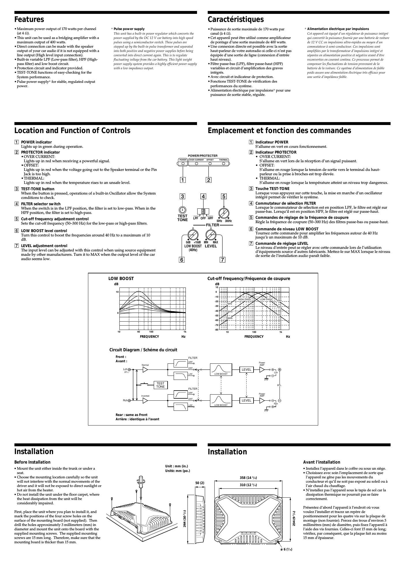
m POWER indicator

Lights up in green during operation.

PROTECTOR indicator

' OVER CURRENT:
Lights up in red when receiving a powerful signal.

0 OFFSET:
Lights up in red when the voltage going out to the Speaker terminal or the Pin
Jack is too high.

' THERMAL:
Lights up in red when the temperature rises to an unsafe level.

[3] TEST-TONE button
When the button is pressed, operations of a builtsin Oscillator allow the System
conditions to check.

IE] FILTER selector sw itch
When the switch is in the LPF position, the filter is set to lowApass. When in the
HPF position, the filter is set to highspass. TEST

E Cut-off frequency adjustment control TONE

Sets the cutoff frequency (507300 Hz) for the l()W*paSS or highspass filters.
E] LOW BOOST level control

Turn this control to boost the frequencies around 40 Hz to a maximum of 10
dB.

LEVEL adjustment control
The input level can be adjusted with this control when using source equipment
made by other manufacturers. Turn it to MAX when the output level of the car
audio seems low.


(40Hz)

POWER/PROTECTER

ma ovcacuaazm oFFsEr msmt
O

LPF OFF HPF
FILTER-
o


LOW BOOST LEVEL

peids assure uhe hhmeuttitieh ileeh-iyue HE'S cftitacc pent
he sortie uiihptunheefethle.

integrés.

I Avec circuit et indicateur de protection.

I Fonctions TEST-TONE de verification des
performances du systeme.

I Alimentation électrique par impulsions* pour une
puissance de sortie stable, régulée.

-
Emplacement et fonction cles commandes

lndicateur POWER

S'allume en vert en cours fonctionnernent.

lndicateur PROTECTO R
' OVER CURRENT:
Sallume en vert lors de la réception d'un signal puissant.
' OFFSET:
S'allume en rouge lorsque la tension de sortie vers le terminal du haut-
parleur ou la prise a broches est trop élevée.
' THERMAL:
S'allume en rouge lorsque la temperature atteint un niveau trop dangereux.

Touche TEST-TO N E
Lorsque vous appuye sur cette touche, la mise en marche dun oscillateur
inte'gre' permet de véri er le systeme.

E Commutateur de selection FILTER
Lorsque le commutateur de selection est en position LFF, le filtre est regle sur
passesbas. Lorsqu'il est en position HFF, le filtre est re'gle' sur passeshaut.

E Commandes de réglage de la fréquence de coupure
Regle la fréquence de coupure (507300 Hz) des filtres passesbas ou passeshaut.

@ Commande de niveau LOW BOOST
Tournez cette commande pour amplifier les fréquences autour de 40 Hz
jusqua un maximum de 10 dB.

Commande de réglage LEVEL
Le niveau d'entrée peut se re'gler avec cette commande lors de l'utilisation
d'e'quipements source d'aut'res fabricants. MetteZsle sur MAX lorsque le niveau
de sortie de l'installation audio parait faible.

o o
50th SoflHz

LOW BOOST
dB

to

Cut-off frequency/Fréquence de coupure

dB
10

Arriére : identique a I'avant

~40
I}
-50
60
-7D
~80
1|]
FREQUENCY Hz FREQUENCY Hz
Circuit Diagram / Schéme du circuit
0" FILTER
Avant:
/ tells
c > Waste > es
5' -rpp l Lowaoosr Feb
1 1 an
FILTER: i
fits 3 z
Rm i> onsets p
\ W 75°
Rea

Installation

Before Installation

I Mount the unit either inside the trunk or under a
seat.

I Choose the mounting location carefully so the unit
will not interfere with the normal movements of the
driver and it will not be exposed to direct sunlight or
hot air from the heater.

I Do not install the unit under the floor carpet, where
the heat dissipation from the unit will be
considerably impaired.

Unit : mm (in.)
Unite: mm (pm)

First, place the unit where you plan to install it, and
mark the positions of the four screw holes on the
surface of the mounting board (not supplied). Then
drill the holes approximately 3 millimeters (mm) in
diameter and mount the unit onto the board with the
supplied mounting screws. The supplied mounting
screws are 15 mm long. Therefore, make sure that the
mounting board is thicker than 15 mm.

264 (10 1/1)

Installation

Avant l'installation

I lnstallez lappareil dans le coffre ou sous un siege.

I Choisissez avec soin lemplacement de sorte que
lappareil ne gene pas les mouvements du
conducteur et quil ne soit pas expose au soleil ou a
lair chaud du chauffage.

I Ninstallez pas lappareil sous le tapis de sol car la
dissipation thermique ne pourrait pas se faire
correctement.

358 (14 Va)

310 (12 1[4)

° 00mm: °

Irésentez dabord l'appareil a lendroit ou vous
voulez linstaller et tracez un repere de
positionnement pour les quatre vis sur la plaque de
montage (non foumie). Percez des trous denviron 3
millimetres (mm) de diametre, puis fixez lappareil a
laide des vis fournies. Celles-ci font 15 mm de long;
vérifiez, par consequent, que la plaque fait au moins
15 mm d/épaisseur.

B4 (9 lIn)

B 6 (l-)