Sony xm 754 hx owners manual

This is the 19 pages manual for sony xm 754 hx owners manual.
Read or download the pdf for free. If you want to contribute, please mail your pdfs to info@audioservicemanuals.com.

Page: 1 / 19
left right
sony xm 754 hx owners manual

Extracted text from sony xm 754 hx owners manual (Ocr-read)


Page 1

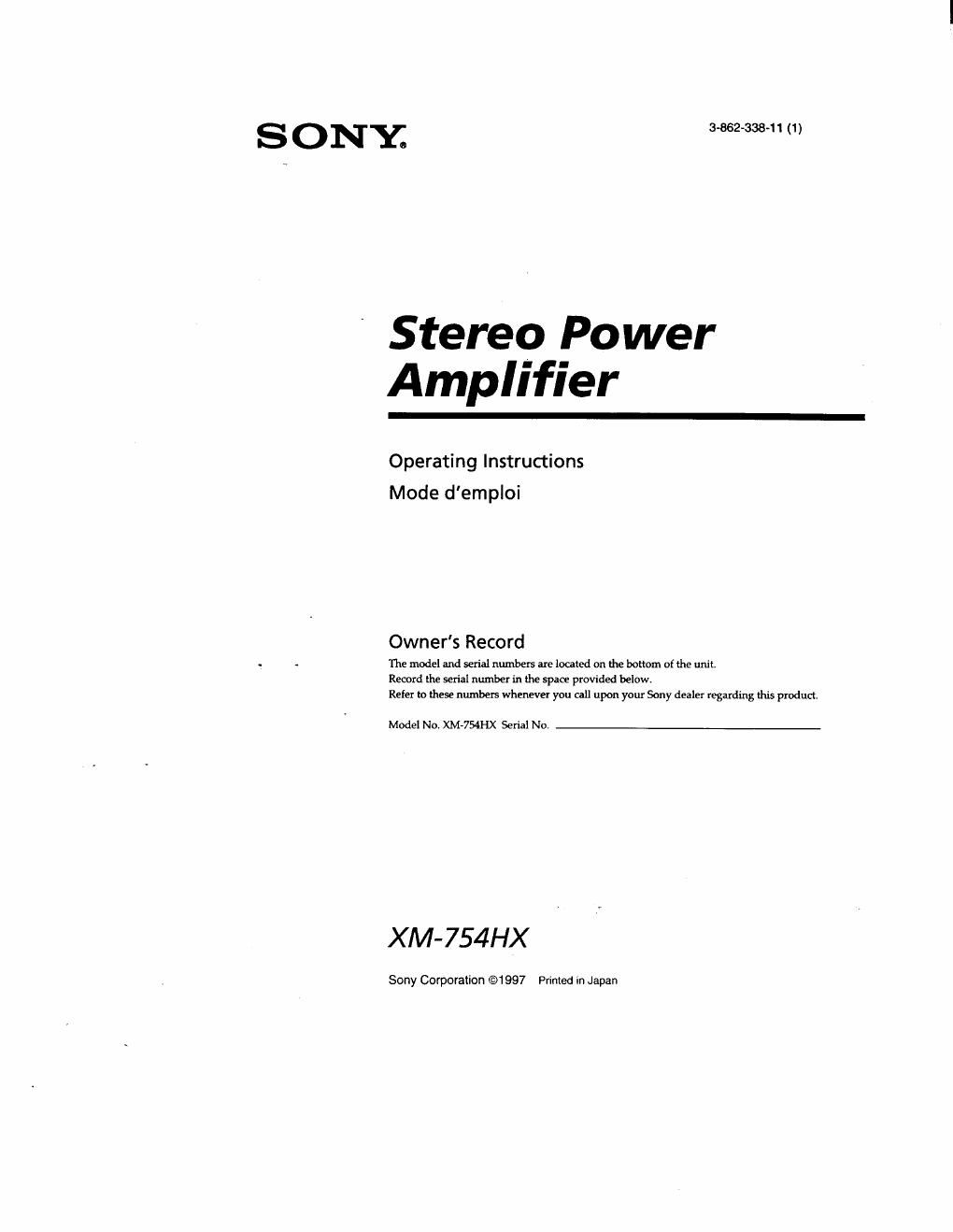
S 0 NY; 3-862-338-11 (1)

Stereo Power
Amplifier

Operating Instructions
Mode demploi

Owner's Record

.. . The model and serial numbers are located on the bottom of the unit.
Record the serial number in the space provided below.
Refer me these numbers whenever you call upon your Sony dealer regarding this product.

Model No. XM-754HX Serial No.

XM-754HX

Sony Corporation @1987 Printed in Japan

Page 2

r - a
S peciflcatlons
Cimmerie Circuit OTL (Sonia 5am Dimnion harmonique 0.)5 1» nu inférieure (a lid-ll, 4 D]
transfomateur) Plage de réglage du niveau d'entrée
Alimenlation par impulsions 0.2 - 4.0 v (prises a more RCA)
Entrées P1136 i brodie RCA 0,4 - 8,0 V (entrée hint nivelu)
Sonics Borne: de hut-parieurs Filtre pane-hank 50 - 200 Hz, -lZ dB/od
lmpédance des haut-parleurs Film passe-has 50 - 200 Hz, -12 dB/oct
l' - s n (stéréo) Amplification do basses iréquences
2 - 8 0 (utilisé comma amplificateur 0 - 10 dB (40 Hz)
en pom) Alimentation Batterie de vulture, mam confinu
Sonics maximales (HICURRENT/ Hl-VOLTAGE) 12 V (masse négative)
Quatre haut-parleurs : Tension d'alimeniatlun 10,5 - 16 V
90/170W x 4 (a 4 n) Courant i la sortie nominale: 40 A
Tmis haut-plrleuis: (mod: HFVOLTACE AD)
90Wx2+750WXlll70WX2e Entréedetélécommande:l.5mA
toonuam) rDimemians Env.758x50x320mm
Deuxhaut-parleuis: (IIhIngl/uzxul. p0.)
zsouoownram) capu ndeprotcctiondebome
Sonics nominales (HI-CURRENT/ HI-VOLTAGE) mmpris
(tension d'alimemation de 14,4 V) Poids Env. 3,5 kg (7 Ii. n on.) accessoirm

Guam haut-parleurs :

mm campus

35/75Wx4(20Hz-mkflz,0,0¢% Acwssoirafoumis Visdemontagefl)

THD,340) Cadmdebomefl)

SOIIWWxHZOHz-ZflkHLOJ'X, Ammenoption Cordondemnmxionpour

THD. a 2 n) unplificateur de puissanoe RC46

Dcux haut-parleurs :

.1326?!ng (1° "1 ' z W 0.1 5" La mpaon a les spécifications peuvent are modifiées
Réponseenlréquenoe ska-50mm) Pm

' til-CURRENT uniquement

Troubleshooting Guide

The following checklist will assist in the correction of most problems which you may encounter with your unit,
Before going through the checklist below, refer to the connection and operating procedures,

Problem .

The POWER/PROTECTOR
indicator does not light up.

Cause/Solution
The fuse is blown. -~ Replace the (use with a new one.

The ground lead is not securely connected --> Fasten the ground lead securely
to a metal point at the car.

The voltage going into the remote terminal is too low.
- Theoomiec'Iedn-iasteriuutisnutmrned m-OTumon themasterumt.
o The system employs too many amplifiers, »-» Use a relay.

Check the battery voltage (1an - 16 V),

The OVER CURRENT indicator light up Turn off the

in amber.

er switch. The speaker outputs are shortrcircuite¢ -~ Rectify

the cause of a short-circuit.

The OFFSET indicator lights up in
amber.

Turn off the power switch. Make sure the speaker cord and ground lead are
securely connected

The THERMAL indicator lights up in
amber.

The unit heas up abnormally.

- Use speakers with suitable impedanm. ,
~ til-CURRENT mode: 1 to 8 fl.
- Ill-VOLTAGE mode: 2 to 8 (I.
Use HICURRENT mode to'reduce generated heat.

0 Mike sure to place the unit in a well ventilated location.

Alternator noise is heard.

The power connectinfileads are installed too close to the RCA pin Cords. _..
Keep the leads away cm the cords.

The ground lead is not securely cemented. --> Fasten the ground lead securely
to a metal point of the car.

Negative speaker leads are touching the car chassis. -> Keep the leads away
from the car chassis.

The sound is muffled.
r

The sound ls too low.

The FlLTER switdn is set to the LPF" position.

The lei/el achusnnent control is set to the MIN position