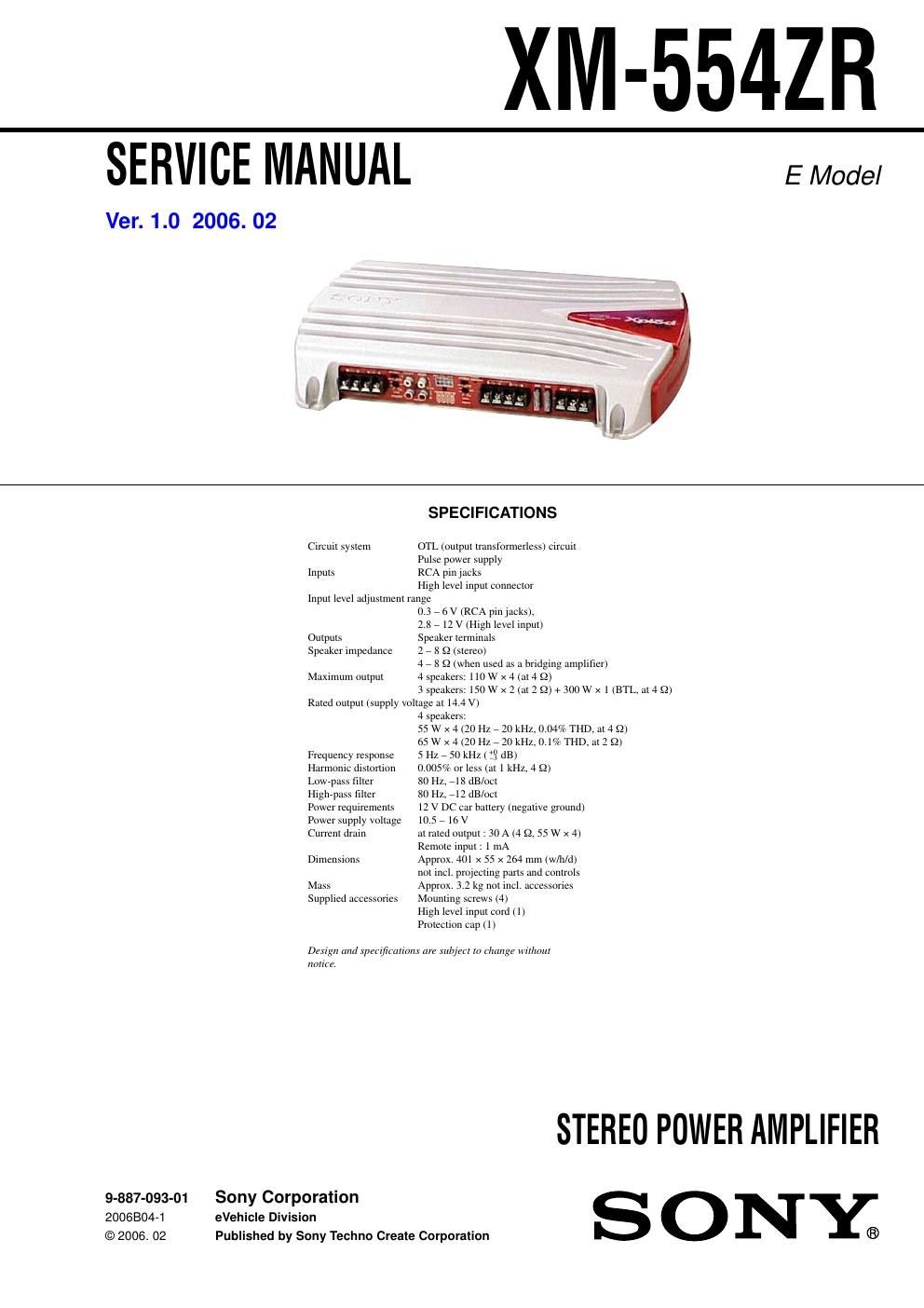
Sony xm 554 zr service manual

This is the 22 pages manual for sony xm 554 zr service manual.
Read or download the pdf for free. If you want to contribute, please mail your pdfs to info@audioservicemanuals.com.

Page: 1 / 22
left right
sony xm 554 zr service manual

Extracted text from sony xm 554 zr service manual (Ocr-read)


Page 1

2 TABLE OF CONTENTS 1. GENERAL Location and Function of Controls .......................................... 3 Connections ............................................................................. 4 2. DISASSEMBLY 2-1. Bottom Plate ........................................................................ 7 2-2. AMP Board Section ............................................................ 8 2-3. Panel (Front) ........................................................................ 8 3. DIAGRAMS 3-1. Block Diagram .................................................................... 9 3-2. Printed Wiring Board ........................................................ 11 3-3. Schematic Diagram -“AMP Section (1/2)-“ ........................ 12 3-4. Schematic Diagram -“AMP Section (2/2)-“ ........................ 13 4. EXPLODED VIEWS 4-1. Heat Sink (Main) Section .................................................. 15 4-2. AMP Board Section .......................................................... 16 5. ELECTRICAL PARTS LIST ........................................ 17 XM-554ZR PROTECTOR OPERATION CHECK Thermal Protect 1. Short across TH901 with the power on. 2. Verify that the protector is operated and LED901 illuminates red. 3.Verify that the protector is released and LED901 illuminates green when the short is removed. 4. Likewise, perform items 1 to 3 for TH902 and TH903. Over Current Protect 1. Short between the positive and negative sides of the speaker output terminals CN903 and CN904 with the power on. (Perform this shorting for each channel on FRONT and REAR.) 2. Verify that the protector is operated and LED901 illuminates red. 3. Verify that the protector is not released and LED901 remains red even when the short is removed. 4.Verify that the protector is released and LED901 illuminates green when the power is turned off and then on again. Offset Protect 1. Short between the +12V terminal of CN905 and the (L+R) + or (L+R) -“ of the speaker output terminal CN904. (Short between +12V terminal and (L+R) + and between +12V terminal and (L+R) -“.) 2. Verify that the protector is operated and LED901 illuminates red. 3. Verify that the protector is not released and LED901 remains red even when the short is removed. 4.Verify that the protector is released and LED901 illuminates green when the power is turned off and then on again. SAFETY-RELATED COMPONENT WARNING!! COMPONENTS IDENTIFIED BY MARK 0 OR DOTTED LINE WITH MARK 0 ON THE SCHEMATIC DIAGRAMS AND IN THE PARTS LIST ARE CRITICAL TO SAFE OPERATION. REPLACE THESE COMPONENTS WITH SONY PARTS WHOSE PART NUMBERS APPEAR AS SHOWN IN THIS MANUAL OR IN SUPPLEMENTS PUBLISHED BY SONY. UNLEADED SOLDER Boards requiring use of unleaded solder are printed with the lead free mark (LF) indicating the solder contains no lead. (Caution: Some printed circuit boards may not come printed with the lead free mark due to their particular size.) : LEAD FREE MARK Unleaded solder has the following characteristics. - Unleaded solder melts at a temperature about 40°C higher than ordinary solder. Ordinary soldering irons can be used but the iron tip has to be applied to the solder joint for a slightly longer time. Soldering irons using a temperature regulator should be set to about 350°C. Caution: The printed pattern (copper foil) may peel away if the heated tip is applied for too long, so be careful! -Strong viscosity Unleaded solder is more viscous (sticky, less prone to flow) than ordinary solder so use caution not to let solder bridges occur such as on IC pins, etc. -Usable with ordinary solder It is best to use only unleaded solder but unleaded solder may also be added to ordinary solder. Notes on Chip Component Replacement -Never reuse a disconnected chip component. -Notice that the minus side of a tantalum capacitor may be damaged by heat.

Page 2

3 XM-554ZR SECTION 1 GENERAL This section is extracted from instruction manual. Location and Function of Controls Emplacement et fonction des commandes Ubicación y función de los controles POWER/ PROTECTO R 1POWER/PROTECTOR indicator Lights up in green during operation. When the PROTECTOR is activated the indicator will change from green to red. When the PROTECTOR is activated refer to the Troubleshooting Guide. 2LEVEL adjustment control The input level can be adjusted with this control. Turn it in the clockwise direction when the output level of the car audio unit seems low.3HPF switch When the HPF switch is set to ON, the High- pass filter (80 Hz) is effective. 4LPF switch When the LPF switch is set to ON, the Low- pass filter (80 Hz) is effective. 1Indicateur POWER/PROTECTOR Sallume en vert en cours de fonctionnement. Lorsque PROTECTOR est activé, lindicateur passe du vert au rouge. Lorsque PROTECTOR est activé, reportez- vous au Guide de dépannage. 2Commande de réglage LEVEL Le niveau dentrée peut se régler avec cette commande. Tournez cette commande dans le sens des aiguilles dune montre lorsque le niveau de sortie de lautoradio semble faible.3Commutateur HPF Lorsque le commutateur HPF est réglé sur ON, le filtre passe-haut (80 Hz) est activé. 4Commutateur LPF Lorsque le commutateur LPF est réglé sur ON, le filtre passe-bas (80 Hz) est activé. 1Indicador POWER/PROTECTOR Se ilumina en verde durante el uso. Si se activa PROTECTOR, el indicador cambiará de verde a rojo. Si se activa PROTECTOR, consulte la Guía de solución de problemas. 2Control de ajuste LEVEL Mediante este control se puede ajustar el nivel de entrada. Gírelo en el sentido de las agujas del reloj si el nivel de salida del sistema de audio para automóvil parece bajo.3Interruptor HPF Cuando el interruptor HPF está ajustado en ON, se activa el filtro de paso alto (80 Hz). 4Interruptor LPF Cuando el interruptor LPF está ajustado en ON, se activa el f iltro de paso bajo (80 Hz). (80Hz)LPF LEVELREAR OFF ON1 2 4 60.3V0.5 (80Hz) HPF LEVELFRONT OFF ON1 2 4 60.3V0.5 Precautions-This unit is designed for negative ground 12 V DC operation only. -Use speakers with an impedance of 2 to 8 -„¦ (4 to 8 -„¦ when used as a bridging amplifier). -Do not connect any active speakers (with built- in amplifiers) to the speaker terminals of the unit. Doing so may damage the active speakers. -Avoid installing the unit in areas subject to: -high temperatures such as from direct sunlight or hot air from the heater -rain or moisture -dust or dirt. -If your car is parked in direct sunlight and there is a considerable rise in temperature inside the car, allow the unit to cool down before use. -When installing the unit horizontally, be sure not to cover the fins with the floor carpet etc. -If this unit is placed too close to the car audio unit or aerial, interference may occur. In this case, relocate the amplifier away from the car audio unit or aerial. -If no power is being supplied to the car audio unit, check the connections. -This power amplifier employs a protection circuit* to protect the transistors and speakers if the amplifier malfunctions. Do not attempt to test the protection circuits by covering the heat sink or connecting improper loads. -Do not use the unit on a weak battery as its optimum performance depends on a good power supply. -For safety reasons, keep your car audio unit volume moderate so that you can still hear sounds outside your car. Fuse ReplacementIf the fuse blows, check the power connection and replace both the fuses. If the fuse blows again after replacement, there may be an internal malfunction. In such a case, consult your nearest Sony dealer. WarningWhen replacing the fuse, be sure to use one matching the amperage stated above the fuse holder. Never use a fuse with an amperage rating exceeding the one supplied with the unit as this could damage the unit. * Protection circuit This amplifier is provided with a protection circuit that operates in the following cases: -when the unit is overheated -when a DC current is generated -when the speaker terminals are short-circuited. The colour of the POWER/PROTECTOR indicator will change from green to red, and the unit will shut down. If this happens, turn off the connected equipment, take out the cassette tape or disc, and determine the cause of the malfunction. If the amplifier has overheated, wait until the unit cools down before use. If you have any questions or problems concerning your unit that are not covered in this manual, please consult your nearest Sony dealer. Précautions-Cet appareil est conçu pour fonctionner uniquement sur un courant de 12 V CC avec masse négative. -Utilisez des haut-parleurs dune impédance appropriée de 2 à 8 -„¦(stéréo), 4 à 8 -„¦ (en cas dutilisation comme amplificateur en pont). -Ne raccordez pas de haut-parleurs actifs (avec amplificateurs intégrés) aux bornes des haut- parleurs de cet appareil. Cela risquerait en effet dendommager les haut-parleurs actifs. -Ninstallez pas lappareil dans des endroits soumis : - à des températures élevées, comme en plein soleil ou près du chauffage ; - à la pluie ou à lhumidité ; - à la poussière ou à la saleté. -Si votre voiture est garée en plein soleil et que la température a considérablement augmenté à lintérieur de lhabitacle, laissez lappareil refroidir avant de lutiliser. -Si vous installez lappareil à lhorizontale, ne recouvrez pas les ailettes de ventilation avec le tapis de sol ou quoi que ce soit dautre. -Si cet appareil est placé trop près de lautoradio ou de lantenne, il se peut que des interférences se produisent. Dans ce cas, éloignez lamplificateur de lautoradio ou de lantenne. -Si lautoradio nest pas alimenté, vérifiez les connexions. -Cet amplificateur de puissance est équipé dun circuit de protection * conçu pour protéger les transistors et les haut-parleurs en cas de défaillance de lamplificateur. Nessayez pas de tester lefficacité des circuits de protection en recouvrant le dissipateur thermique ou en effectuant de mauvaises connexions. -Nutilisez pas lappareil avec une batterie faible, car sa performance optimale dépend dune bonne alimentation en électricité. -Pour des raisons de sécurité, maintenez le volume de lautoradio à un niveau modéré afin dentendre les bruits extérieurs. Remplacement du fusibleSi le fusible fond, vérifiez les connexions de lalimentation et remplacez le fusible. Si le fusible fond de nouveau après avoir été remplacé, cela peut révéler une défaillance interne de lappareil. Dans ce cas, consultez votre distributeur Sony le plus proche. AvertissementLorsque vous remplacez le fusible, veillez à utiliser un fusible dont la capacité en ampères correspond à celle inscrite sur le porte-fusible. Nutilisez jamais de fusible dont la capacité dépasse celle du fusible fourni avec lappareil car cela pourrait endommager lappareil. *Circuit de protectionCet amplificateur est fourni avec un circuit de protection qui entre en fonction dans les cas suivants : - lorsque lappareil est en surchauffe ; - lorsquun courant continu est généré ; - lorsque les bornes de haut-parleur sont court- circuitées. La couleur de lindicateur POWER/PROTECTOR passe du vert au rouge et lappareil se met hors tension. Dans ce cas, éteignez les appareils raccordés, retirez la cassette ou le disque et déterminez lorigine du problème. Si lamplificateur est en surchauffe, attendez quil refroidisse avant dutiliser lappareil. Si vous avez des questions ou des problèmes concernant votre appareil qui ne sont pas abordés dans ce mode demploi, adressez-vous à votre distributeur Sony le plus proche. Sustitución del fusibleSi el fusible se funde, compruebe la conexión de alimentación y sustituya ambos fusibles. Si el fusible se funde de nuevo después de sustituirlo, es posible que exista un fallo de funcionamiento interno. En este caso, póngase en contacto con el distribuidor Sony más próximo. AdvertenciaAl sustituir el fusible, asegúrese de utilizar uno cuyo amperaje coincida con el especificado en el portafusible. No utilice nunca un fusible con un amperaje superior al del suministrado con la unidad, ya que podría dañar la unidad. *Circuito de protección Este amplificador dispone de un circuito de protección que se activa en los siguientes casos: -Si la unidad se calienta excesivamente -Si se genera corriente cc -Si los terminales de altavoz se cortocircuitan. El color del indicador POWER/PROTECTOR cambiará de verde a rojo y la unidad se desactivará. Si esto ocurre, desactive el equipo conectado, extraiga la cinta de casete o el disco y determine la causa del fallo de funcionamiento. Si el amplificador se ha sobrecalentado, espere hasta que la unidad se enfríe antes de volver a utilizarla. Si desea realizar alguna consulta o solucionar algún problema relativos a la unidad que no aparezcan en este manual, póngase en contacto con el distribuidor Sony más próximo. Precauciones-Esta unidad está diseñada para utilizarse sólo con cc de 12 V negativo a masa. -Emplee altavoces con impedancia de 2 a 8 -„¦ (de 4 a 8 -„¦ cuand se utilice como amplificador en puente). -No conecte altavoces activos (con amplificadores incorporados) a los terminales de altavoz de la unidad, ya que puede dañar dichos altavoces. -Evite instalar la unidad en lugares expuestos a: -altas temperaturas, como a la luz solar directa o al aire caliente de la calefacción -la lluvia o la humedad -suciedad o polvo. -Si aparca el automóvil bajo la luz solar directa y se produce un considerable aumento de temperatura en el interior, deje que la unidad se enfríe antes de utilizarla. -Si instala la unidad horizontalmente, asegúrese de no cubrir las aletas con la moqueta del suelo, etc. -Si coloca la unidad demasiado cerca del sistema de audio para automóvil o de la antena, pueden producirse interferencias. En este caso, instale el amplificador alejado de dichos dispositivos. -Si el sistema de audio para automóvil no recibe alimentación, compruebe las conexiones. -Este amplificador de potencia emplea un circuito de protección * para proteger los transistores y los altavoces en caso de que dicho amplificador presente fallos de funcionamiento. No intente someter a prueba los circuitos de protección cubriendo el disipador de calor o conectando cargas inadecuadas. -No utilice la unidad si la batería se está agotando, ya que el rendimiento óptimo de dicha unidad depende de un buen suministro de alimentación. -Por razones de seguridad, mantenga el volumen del sistema de audio para automóvil en un nivel moderado de forma que sea posible oír los sonidos del exterior del automóvil.