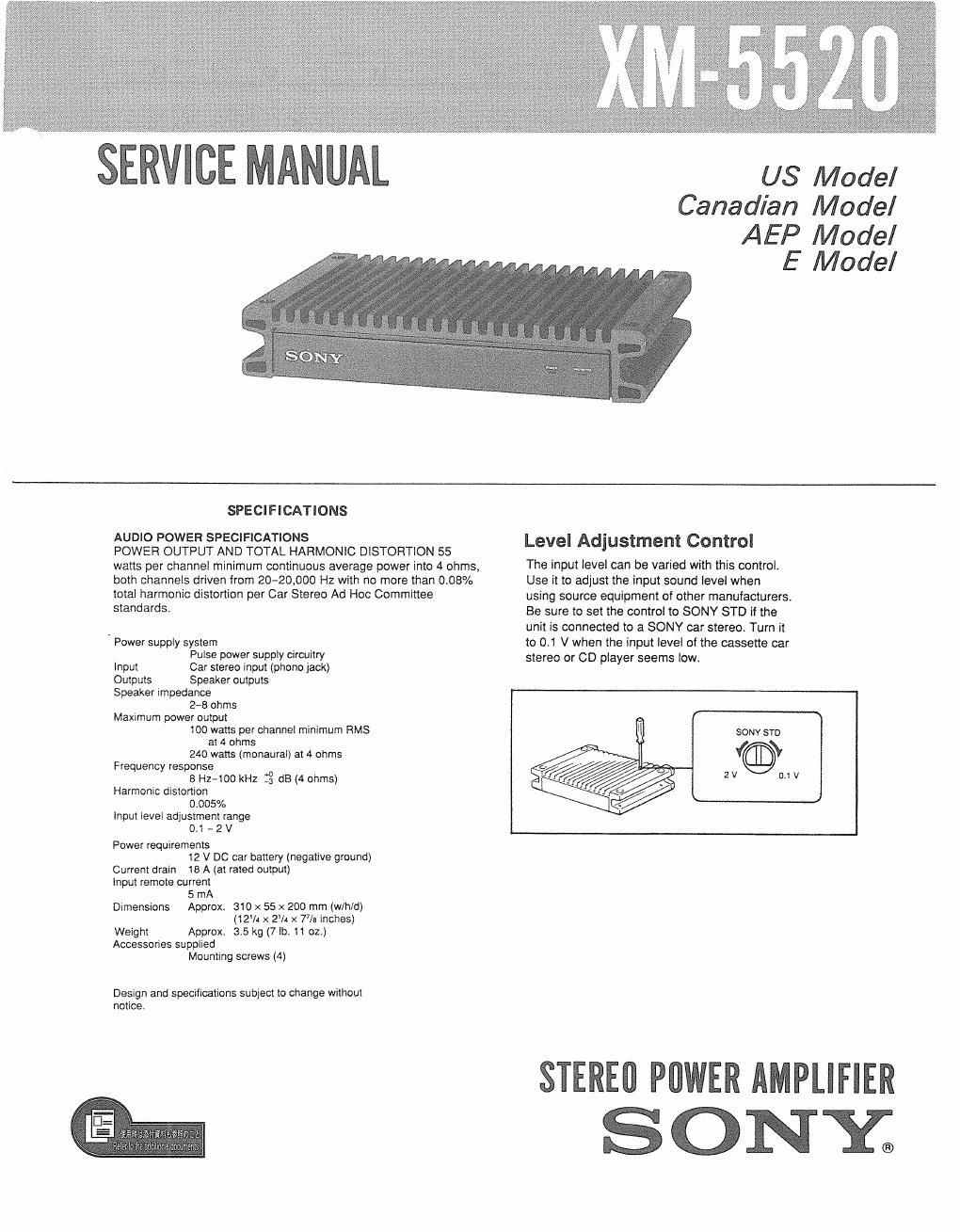
Sony xm 5520 service manual

This is the 10 pages manual for sony xm 5520 service manual.
Read or download the pdf for free. If you want to contribute, please mail your pdfs to info@audioservicemanuals.com.

Page: 1 / 10
left right
sony xm 5520 service manual

Extracted text from sony xm 5520 service manual (Ocr-read)


Page 1

US Model
Canadian Model

AEP Model
E Model

SPECIFICATIONS

AUDIO POWER SPECIFICATIONS

POWER OUTPUT AND TOTAL HARMONIC DISTORTION 55
watts per channel minimum continuous average power into 4 ohms,
both channels driven from 2020,000 Hz with no more than 008%
total harmonic distortion per Car Stereo Ad Hoc Committee
standards.

Power supply system
Pulse power supply circuitry

Input Car stereo input (phone jack)
Outputs Speaker outputs
Speaker impedance

278 ohms

Maximum power output

100 watts per channel minimum RMS

at 4 ohms

240 watts (monaural) at 4 ohms
Frequency response

a Hz-too kHz :3 dB (4 ohms)
Harmonic drslomon

0.005%
Input level adjustment range

0.1 , 2 V
Power requirements

12 V DC car battery (negative ground)
Current drain is A (at rated output)
lnput remote current

5 mA
Dimensions Approx. 310 x 55 x 200 mm (w/h/d)

(12W x 2W x 7% inches)

Weight Approx. 3.5 kg (7 lbs 11 oz.)
Accessories supplied

Mounting screws (4)

Design and specifications subject to change without
notice

Level Adjustment Control

The input level can be varied with this control.
Use it to adjust the input sound level when
using source equipment of other manufacturers
Be sure to set the control to SONY STD if the
unit is connected to a SONY car stereo Turn it
to 01 V when the input level of the cassette car
stereo or CD player seems low.

SONV STD

2V


STEREI] PflWER AMPLIFIER

SONY;

Page 2

XM-5520

SECTION 1
DlSASSEMBLY

Nata: Follow the disassembly procedure in the numerical order given LED BOARD
COVER (BOTTOM)

Panel (Front)

0+KTP3X6

9 Cover (Bottom)

8

DIN BOARD, SPEAKER BOARD, POWER BOARD

Panel (Rear)
9+ BTP3 X 8


9+BTP3><8

A?

Fuse, Holder
@Power board

9 Speaker board

Panel (Rear)

0 Main board

o+BTP3x8


0+P2><8 mamm

o +BTP3><8