Sony xm 440ex

This is the 18 pages manual for sony xm 440ex.
Read or download the pdf for free. If you want to contribute, please mail your pdfs to info@audioservicemanuals.com.

Page: 1 / 18
left right
sony xm 440ex

Extracted text from sony xm 440ex (Ocr-read)


Page 1

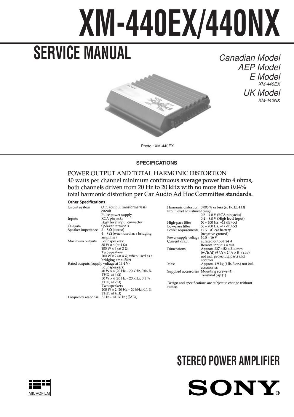
XNI-440EX/440NX

SERVICE MANUAL

Photo : XM-44OEX

Canadian Model
AEP Model
E Model

X M»440EX

UK Model

XM-440NX

I.-
MICROFILM

SPECIFICATIONS

POWER OUTPUT AND TOTAL HARMONIC DISTORTION

40 watts per channel minimum continuous average power into 4 ohms,
both channels driven from 20 Hz to 20 kHz with no more than 0.04%
total harmonic distortion per Car Audio Ad Hoc Committee standards.

Other Specifications

Circuit system OTL (output transtomerless)
circuit
Pulse power supply
Inputs RCA pin jacks
High level input. connector
Outputs Speaker terminals

Speaker impedance 2 A 8 (2 (stereo)
4 v 8 {2 (when used as a bridging
amplifier)

Maximum outputs Four speakers:
80 W X 4 (at 4 D)
100 W x 4 (at 2 9)
Two speakers:
200 W x 2 (at 4 9, when used as a
bridging amplifier)

Rated outputs (supply voltage at 14.4 V)
Four speakers:
40 W X 4 (20 Hz 7 20 Hi], 0.04 /u
THD, at 4 n)
50 W X 4 (20 Hz , 20 kHz,ll.l "A
THD, at 2 n)
Two speakers:
lDOWthZOHz-ZOkHz,0.l %
THD, at 4 n)

Frequency response 5 Hz - 100 kHz (:3 dB)

Harmonic distortion

0.005 /0 or less (at IkHz, 4 (I)

Input level adjustment range

iiighpass filter
Low-pass filter
Power requirements

Power supply voltage
Current drain

Dimensions

Mass

Supplied accessories

0.2 , 4.0 v (RCA pin jacks)

0.4 - 8.0 V (High level input)

50 - 200 HZ, ~12 dB/oct

50 - 200 Hz, -12 dB/oct

12 V DC car battery

(negative ground)

10.5 - 16 V

at rated output: 24 A

Remote input: 14 mA

Approx. 257 x 52 x 214 mm
(w/h/d) (93/ax 2 Vs >< 8 /z in.)
not incl. prolecting parts and
controls

Approx. L9 kg (4 lb. 3 02.) not incl.
accessories

Mounting screws (4);

Terminal Cap (1)

Design and specifications are subject to change without

notice.

STEREO POWER AMPLIFIER
S O NY®

Page 2

TABLE OF CONTENTS

Specifications ............................................................................. l
1. GENERAL ....................................................................... 3
2. DISASSEMBLY

21. Main Board Removal .
3. DIAGRAMS

3-1. Block Diagram ........

3-2. Printed Wiring Boards

3-3. Schematic Diagrams iMAIN (1/2) Section 7.

3A4. Schematic Diagrams iMAIN (2/2) Section 7.
4. EXPLODED VIEW ...................................................... 12
5. ELECTRICAL PARTS LIST .................................... 12