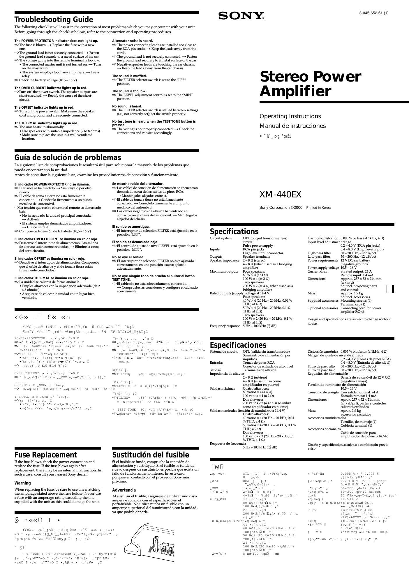
Sony xm 440 ex owners manual

This is the 4 pages manual for sony xm 440 ex owners manual.
Read or download the pdf for free. If you want to contribute, please mail your pdfs to info@audioservicemanuals.com.

Page: 1 / 4
left right
sony xm 440 ex owners manual

Extracted text from sony xm 440 ex owners manual (Ocr-read)


Page 2

-
Features

I Maximum power output of 80 watts per channel (at 4 ohms).

I This unit can be used as a bridging amplifier with a maximum output of
200 watts.

I Direct connection can be made with the speaker outputs of your car
audio if it is not equipped with the line output (High level input
connection).

I Built-in variable LIF (Low-pass filter) and HIF (High-pass filter).

I Protection ci.rcuit*I and indicator provided.

I Pulse power supply*2 for stable, regulated output power.

*1 Protection circuit
This miiplifier is pmpiahal with a pthtactiau circuit that nelnmlcs lll thafallawihg
cascs.
7 wllcli the lmii is over/tented
7 whau a DC current is gahtmttd
7 Tulicll the spcakcr terminals are Sllfll'l-EilCllihd.
The color oflllc POWER/PROTECTOR indicator will Llzmzxefmm gram in red,
and the unit will shill down.
lflhis hnppehs, tum afftht connected sauipmaht. taka out [111' (nsseltc inpc of disc,
anal determine the enusc aftha iiialfuhmah. [ft/it amplifier has mahmtsd, wail
until tha unit with usual hafm usmg again.

*2 Pulse power supply
This will has a built-in poulcr regulator which callzlcrts the pomcr supplied by the
DC 12 V cm llllltery iiita high spml pulses using a semiconductor smith. Thesa
pulses are slcppcd up by the built-ill plllst Inmsfariilcr and separated ihta bath
pusltive and mgativa pawe? suppllcs Wm haihg mum-mil mil! direct current
again This is it regulattfluttuatihg voltage fruit] tht car battery This light might
pUiDEl' supply system provides a highly sfficieul pvmcr supply with a low
imptuahcs output.

-
Location and Function of Controls

El POW ERIPROTECTO R indicator

I OFFSET lights up in green during normal operation. The color
will change from green to red when the voltage going out to
the speaker terminal or the pin Jack is too high.

I THERMAL lights up in green during normal operation. The
color will change from green to red when the temperature rises
to an unsafe level. The color will return to green when the
temperature returns to normal.

I OVER CURRENT lights up in green during normal operation.
The color will change from green to red when receiving a
powerful signal.

Cut-off frequency adjustment control (FRONT/ REAR)

Sets the cutoff frequency (507200 Hz) for the low7pass or high7
pass filters.

El FILTER selector sw itch (FRO NT/ REA R)
When the switch is in the LPF position, the filter is set to low7
pass. When in the llPF position, the filter is set to high7pass.

E LEVEL adjustment control (FRONT/REAR)
The input level can be adjusted with this control when using
source equipment made by other manufacturers. Turn it to MAX
when the output level of the car audio seems low.

E] TEST TONE button
To check the system's status, activate the built7in transmitter then
press the TEST TONE button. If the tone is heard, the unit is
functioning normally.

(right side/lado derecho/yk 1

POWER/
PROTECTOR

-
Caracterlsticas

I Salida maxima de potencia de 80 vatios por canal (a 4 ohmios).

I Esta unidad puede utilizarse como amplificador en puente con una
salida maxima de 200 vatios.

I Es posible realizar la conexion directa con la salida de altavoz de un
sistema de audio para automovil si este no esta equipado con salida de
Linea (Conexion de entrada de alto nivel).

I Filtro de paso bajo (LIF) variable incorporado y filtro de paso alto
(HPF).

I Circuito de proteccion*| e indicador proporcionados.

I Suministro de alimentacion por impulsos": para obtener una potencia
de salida estable y regulada.

*1 Circuito de protection
Este amplificadcr dlspone de un clrcuito de protecclon quese actlva en los
slgulents cases:
7 Si Ia unidad se caliente excsivamente.
7 Si se genera corrlenteCC.
7 Si los terminals de altavoz se cortocircultan.
El color del lndlcador POWER/PROTECTOR camblara deverdea rolo y la
unldad se deactivara.
Sl stc ocurre daactlveel equlpo conectado, e y determlnela causa dd fallo defunclonamiento. Sl el amplificador se ha
sobrecalentado, spere haste que la unidad se enirleants de volve' a utlllzarla.

*2 Suministro de alimentacién par impulsos
Esta unidad disponede un reguladcr de potencia incorporado que convierteei
sumlnlstro deallmentacién de 12 V CC dela baterla del autcmévil en impulses de
alta veiccidad mediante un inte'ruptor semiconductor. Estos impulses 5e
incrementan medianteei transformadcr lnccrpcrado de impulses y se divlden en
sumlnlstro de allmentacién positlva y negative ants devolver a ccnvertlrseen
corrlente directa. D eata forma, se regula la tension fluctuante de la bateria del
automévil. Este slstema de sumlnistro deallmentaclon de p50 reducido
proporclona un su ministro de alta eficacla con una sallda de baja lmpedancla.

-
Ubicacion y funcion de los
controles

[fl lndicador POWER] PROTECTOR

I OFFSET se ilumina en Color Verde durante el funcionamiento
normal. El color cambiara de Verde a rojo si la tension que
recibe el terminal de altavoces o la torna de pines es
demasiado alta.

I THERMAL se ilumina en color Verde durante el
funcionamiento normal. El color cambiara de Verde a rojo si la
temperatura alcanza niveles peligrosos. Dicho color volvera a
ser Verde cuando la temperatura vuelva a ser normal.

I OVER CURRENT se ilumina en color Verde durante el
funcionamiento normal. El color cambiara de Verde a rojo al
recibirse una sefial potente.

Control de ajuste de frecuencia de corte (FRONT/REAR)
Ajusta la frecuencia de corte (50 7 200 Hz) para los filtros de paso
bajo o paso alto.

lnterruptor de seleccién FILTER (FRO NTIREAR)
Si el interruptor se encuentra en la posicion LPF, el filtro se
aj stara en el paso bajo. Al encontrarse en la posicion HPF, el filtro
se ajusta en el paso alto.

[E Control de ajuste de nivel LEVEL (FRONT/REAR)
El nivel de entrada puede ajustarse con este control si se utiliza
un equipo fuente de otros fabricantes. Girelo hasta MAX si el
nivel de salida del sistema de audio del automovil es bajo.

[E Boton TEST TONE
Para comprobar el estado del sistema, active el transmisor
incorporado y después pulse el boton TEST TONE. Si se oye el
tono, significa que la unidad funciona con normalidad.

-
flS'I

InC\n,,DT /]¥\TV5,ZBE Wlfbmfi iAiC

-2;» ¥i¥,§@t /'¥\Tvgm w" swag/3 ,,;<:
- >Y7znTnfi> T2;.. new, gZ¥XiA< T- >n "was;
7 m7 ;] ,,q¥>;z/Jt57 pic
-/"i]¥iz.LPE]§ctqoi penal tqoi Vic
. ti<<0'@uq7"M<< 2; go;c
- >w;(Zl¥X¥\Tv¥,fl true.
*1 «Ofauq,
Y»'£«] a tixfbyH/U7;"p7 ""«o@,iq, ,G
7 2 y» L , fl'
7 iiy:. 7 2 «>n /l u, fl ,-c
POWER/PROTECTOR « Y ,jO""C/ *NY per <1,A¥>) *NXQ **.,,'C

fp"Gth/:o" 7,-p,-A xw :57 ":/x",vAaaeyxi /,-7a'.
) Iii-CfpG'e/3 ,,,,L ,-A Yu Y» §N<

Y» fX/E) /"Xla
"fluqf ' 4m"?
isifbe/A/i ' «(If

sq £iCXo »4 )ti "q

2' « or! [1 some] Mi/m XCL
y,,q/§«stQ/ ( ¥g>tuq' ,-Cxo(o< /F">'wnTiIfl,,q/
tf,Yi*£fl §c" § pzrx'm "fl',,q-

-
JCUTTD 11.f Im'M¥\f1

[fl POWER/PROTECTOR « 2; ;0

I -7/ul E as «-~ti/a.>n,,/,
fb¥c §@f NSTTHK ¥H" f I G,C 1" J l

.1, -;/f",,q g/ fi 1A, 32; ""cr 7N¥ pet < <1} 1c
'fb¥;7/u§@fi THERMAL 32; ¥H" / 2;>n, 32; ""Cf 7N2; aei < (if ;c- .<< < ¥g7fi 1A,
2; Cf 7N fMaef ic
Ifb2;é7vu§@fi QAER CURRENTH; ¥H"aef T«<3;c- fax 7jflE< infi gA, 32; "Cf 7N¥ "aef < (if ;c
"1/ Wivgfis ,77u mom/REAR ;
t] 'wSth', tqod ,,""1/ wool) Hzic

FILTER; nil WONT/REAR ,
- infill iB'LPFf ,mfi iAoi ,,¢],m<
HPEfi 1A'oi ,,t],m< tq'ouic
[E] LEVEL 2; , 7u "mom/REAR ,
- uV2;,u 2;t»sty 2;ii"n-::.:]tn iA¥i¥.f,,77n "is , gz/J,,q2;>
- nTufl> T"";z2;x,,q2;>f ¥G/ scfi iA¥i7N77uMA>§z 1C
[5] TEST TONE
>n )>utt, fpGil 2;n > :2. ,A«h2;»nti,2;\il ¥¢7,c

§C$qoi;C- fut) tB'

orrssr

YHERMAL

Cut-off frequency/Frecuencia de corte!" 1/

Wiv

Circuit Diagram/Diagrama de circuitoS/aq, a V

FlLTER
dB
l\ or;
L h
is in? l/ 1;fo W
(leftside/ladoizquierdo/Y ) 1" . - . l 750
a lfi .
FILTER LEVEL is .. ,_° , 1 MONO
LPF OFF HPF TEST 5 FlLTER:
Ml l
Ellij . TONE KM Eu» 1 . W
5am 2non MIN MAX in w © 1/ 6:.ch
FREQUENCY Hz LPF .

D

FM

Installation

Before Installation

I Mount the unit either inside the trunk or under a seat.

I Choose the mounting location carefully so the unit will not interfere
with the normal movements of the driver, and where it will not be
exposed to direct sunlight or hot air from the heater.

I Do not install the unit under the floor carpet, where the heat dissipation
from the unit will be considerably impaired.

First, place the unit where you plan to install it, and mark the positions of
the four screw holes on the surface of the mounting board (not supplied).
Then drill the holes approximately 3 millimeters (mm) in diameter and
mount the unit onto the board with the supplied mounting screws. The
supplied mounting screws are 15 mm long. Therefore, make sure that the
mounting board is thicker than 15 mm.

@
O

mfifimaimolmo

-
Instalacion

Antes de realizar la instalacién

I Monte la unidad en el interior del maletero o debajo de un asiento.

I Elija cuidadosamente el lugar de instalacion de forma que la unidad no
dificulte los movimientos normales del conductor, y donde ésta no
quede expuesta a la luz solar directa ni al aire caliente de la calefaccion.

I No instale la unidad debajo de la moqueta del suelo, donde la
disipacion de calor de calor de la misma disminuira considerablemente.

En primer lugar, coloque La unidad donde planee instalarla y marque las
posiciones de los cuatro orificios para los tomillos sobre la superficie del
tablero de montaje (no suministrado). A continuacion, perfore los orificios
con un diametro de aproximadamente 3 milimetros (m) y monte la
unidad sobre el tablero con los tornillos de montaje suministrados. Dado
que la longitud de estos tornillos es de 15 mm, compruebe que el grosor del
tablero de montaje sea superior a 15 mm.

4 - a 6

Unit : mm
Unidafl: mm
t f ism

fw, .
fw, ,/§< o2!» ¥ifw, ,tbums f §lé /;A/]¥i¥1-lfw, _fbfiyf 'r/uic
. >n¥JT fag fw,,f ,miA¥Hn"¥» /L.,vQ2;q "2;;7<; "iA/Z/fimn"
u 11§¥oefizfig' in» ,m' Ii ,,,,,D s. etc
-//7N¥» fw,m' faOfa- /U;A§<

>¥ ;A7N¥» 'aefb7z¥- fw,,fa/L;Au¥3fbfw,,O;]¥,,.-£= pm
A: > t v/ f ,m;C M< ...7 ozeipmm 2; / iA¥,-£n Jw,,
¥,T V7N2;» fw, ,jbwam/wtc' ftfwhsmvmndqy 2;l-lm:;T

«05w, ,o"«p« :15 mrth/Wic

Sony®|ine http://www.world.sony.com/