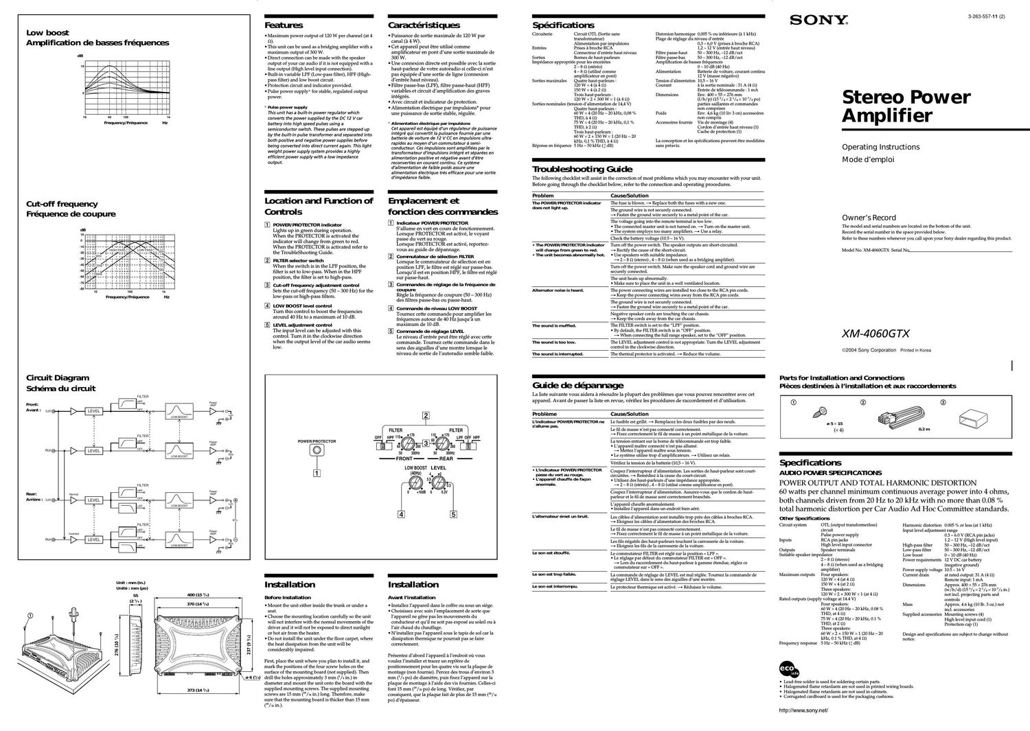
Sony xm 4060 gtx owners manual

This is the 2 pages manual for sony xm 4060 gtx owners manual.
Read or download the pdf for free. If you want to contribute, please mail your pdfs to info@audioservicemanuals.com.

Page: 1 / 2
left right
sony xm 4060 gtx owners manual

Extracted text from sony xm 4060 gtx owners manual (Ocr-read)


Page 2

Connections

Precaltiors

O This unit is designed for negative ground 12 V DC
operation only.

O Use speakers with suitable impedance.

7 2 7 8 9 (stereo), 4 7 8 Q (when used as a
bridging amplifier).

O Do not connect any active speakers (with built-in
amplifiers) to the speaker terminals of the unit.
Doing so may damage the amplifier and active
speakers.

O Avoid installing the unit in areas subject to:

7 high temperatures such as from direct sunlight or
hot air from the heater

7 rain or moisture

7 dust or dirt

O If your car is parked in direct sunlight and there is a
considerable rise in temperature inside the car,
allow the unit to cool down before use.

O When installing the unit horizontally, be sure not to
cover the fins with the floor carpet etc.

O If this unit is placed too close to the car radio or
antenna, interference may occur. In this case,
relocate the amplifier away from the car radio or
antenna.

O If no power is being supplied to the master unit,
check the connections.

O This power amplifier employs a protection circuit*
to protect the transistors and speakers if the
amplifier malfunctions. Do not attempt to test the
protection circuits by covering the heat sink or
connecting improper loads.

O Do not use the unit on a weak battery as its
optimum performance depends on a good power
supply.

O For safety reasons, keep your car audio volume
moderate so that you can still hear sounds outside
your car.

O By default, the FILTER switch is in OFF position.
When connecting the full range speaker, set to the
OFF position.

Fuse Replaoerrmt

If the fuse blows, check the power connection and
replace both the fuses. If the fuse blows again after
replacement, there may be an internal malfunction. In
such a case, consult your nearest Sony dealer.

Vihrrl'ng

When replacing the fuse, be sure to use one matching
the amperage stated above the fuse holder. Never use
a fuse with an amperage rating exceeding the one
supplied with the unit as this could damage the unit.

:r Won drcuit
This amplifier is provided with a protection circuit
that operates in the following cases:
7 when the unit is overheated
7 when a DC current is generated
7 when the speaker terminals are short circuited
The POWER/PROTEC TOR indicator lights up in red and
the unit will shut down.
If this happens, turn off the connected equipment,
take out the cassette tape or disc, and determine the
cause of the malfunction. If the amplifier has
overheated, wait until the unit cools down before
use.

If you have any questions or problems concerning
your unit that are not covered in this manual, please
consult your nearest Sony dealer.

Connexions

I .

Pl'ecattlons

O Cet appareil est concu pour fonctionner uniquement
sur courant continu de 12 V avec masse negative.

O Utilisez des haut-parleurs dune impedance
appropriée.

7 2 7 8 (2 (stereo) , 4 7 8 Q (utilise comme
amplificateur en pont).

O Ne raccordez pas de haut-parleurs actifs (avec
amplificateur integré) aux bornes de haut-parleurs
de cet appareil. Cela risquerait en effet
dendommager I/amplificateur et les haut-parleurs
actifs.

O N installez pas lappareil a un endroit exposé a :

7 des temperatures elevées, par exemple soumis au
rayonnement direct du soleil ou pres d/un
conduit de chauffage

7 la pluie ou a lhumidite

7 de la poussiere ou a des saletés

O Si votre voiture était garee en plein soleil et que la
temperature a considérablement augmenté a
l/intérieur, laissez refroidir Iappareil avant de
l/utiliser.

O Si vous installez l/appareil a lhorizontale, ne
recouvrez pas les ailettes de ventilation par Ie tapis
de sol ou autre chose.

O Si cet appareil est place trop pres de l/autoradio ou
de lantenne, il se peut que des interferences se
produisent. Dans ce cas, éloignez lamplificateur de
l/autoradio ou de lantenne.

O Si Iappareil principal n'est pas alimenté, ve'rifiez les
connexions.

O Cet amplificateur est équipé dun circuit de
protection" destiné a proteger les transistors et les
haut-parleurs en cas dysfonctionnement de
lamplificateur. Ne tentez pas de tester les circuits
de protection en couvrant laccumulateur de chaleur
ou en branchant des charges inadéquates.

O N utilisez pas lappareil sur une batterie faible, car
ses performances optimales dependent dune bonne
alimentation électrique.

O Pour des raisons de sécurité, écoutez lautoradio a
un volume modére afin dentendre les bruits
exterieurs.

O Le réglage par defaut du commutateur FILTER est
o OFF ». Lors du raccordement du haut-parleur a
game étendue, réglez ce commutateur sur « OFF ».

Rerrplaoamt du fus' ble

Si le fusible grille, vérifiez Ie branchement de
Ialimentation et remplacez les deux fusibles. Sil
grille de nouveau apres avoir été remplacé, il est
possible quil y ait un dysfonctionnement interne.
Dans ce cas, consultez votre cdistributeur Sony.

Avertim

En cas de remplacement du fusible, veillez a respecter
lamperage indique au-dessus du logement du
fusible. Nutilisez jamais de fusible dont lampérage

dépasse celui du fusible fourni avec lappareil, car
vous risqueriez dendommager Iappareil.

* Circuit de prutafion
Cet amplificateur est equipé d 'un circuit de
protection qui sactive dans les cas suivants :

7 Surchauffe de lappareil

7 Production dun courant continu

7 Court-circuit aux bornes des haut-parleurs

L indica teur PO WERlPRO TE C TOR sallume en rouge
et l'appareil sarréte.

Si le cas se pre'sente, éteignez tout appareil raccorde
et ejectez la cassette ou le disque compact avant
dexaminer la cause de la defaillance. Si
lamplificateur a surchauffe, attendez quil
refroidisse.

Iour toute question ou probleme qui ne serait pas
traite' dans ce manuel, consultez votre distributeur
Sony.

-

Caution

O Before making any connections, disconnect the
ground terminal of the car battery to avoid short
circuits.

I Be sure to use speakers with an adequate power
rating. If you use small capacity speakers, they
may be damaged.

I Do not connect the 9 terminal of the speaker
system to the car chass , and do not connect the
9 terminal of the right speaker with that of the
left speaker.

O Install the input and output cords away from the
power supply wire as running them close
together can generate some interference noise.

O This unit is a high powered amplifier. Therefore,
it may not perform to its full potential it used
with the speaker cords supplied with the car.

O If your car is equipped with a computer system
for navigation or some other purpose, do not
remove the ground wire from the car battery. It
you disconnect the wire, the computer memory
may be erased. To avoid short circuits when
making connections, disconnect the +12 V power
supply wire until all the other wires have been
connected.

-
Attention

O Avant deffectuer les connexions, debranchez le
fil de masse de la borne de la batterie pour éviter
un courtcircuit.

O Utilisez des bautrparleurs de puissance
adequate. Si vous utilisez des hauteparleurs de
faible capacite, ils risquent detre endommagés.

O Ne raccordez pas la borne e des hautrparleurs a
la carrosserie de la voiture ni la borne @ du
hauteparleur droit a celle du hauteparleur
gauche.

O Eloignez les cordons dentrée et de sortie du fil
d'alimentation electrique pour éviter que des
interferences ne se produisent.

O Cet appareil est un amplificateur de haute
puissance et il peut ne pas atteindre sa puissance
maximale si les cordons de bautrparleurs
originaux de la voiture lui sont raccordes.

O Si votre voiture est e'quipée dun systeme de
navigation on d'un ordinateur de bord, ne
de'branchez pas le fil de masse de la batterie de la
voiture. Si vous debranchez ce fil, toute la
memoire de l'ordinateur sera effacée. Pour e'viter
un courtrcircuit lorsque vous effectuez les
branchements, branchez le fil dalimentation de
+12 V uniquement apres avoir branche tous les
autres fils.

Pasthe wire through the cap, connect
the wits, then oovertheterninals with
the ap.

Note

When you tighten the screw, be careful not to
apply too much torquet as doing so may damage
the screw.

* The torque value should be less than 1 NOm.

Make the terminal connections as illustrated below.
Proce'dez aux connexions des bomes comme illustré ci-dessous.

Faits passer l5 fils par le ache, ramorda
Is fils, puis remuvra Is barns avec le
adme.

Remarque

Lorsque vous vissez la vis, faites attention a ne
pas appliquer une trap grande force", car cela
pourrait endommager la vis,

* Le couple de torsion doit étre inférieur a l NOm.

Power Connection Wires
Cébles d'alimentation

Remote outputi
Sortie de
telecommandet
(REM OUT)

(hr audio
Auholadin

accessoires.


6 lfyou have the factory original or some other car audio without a remote out-put on the amplifier, connect
the remote input terminal (REMOTE) to the accessory power supply.

* Si vous disposez du mode/e dorigine ou dun autre autoradio dont lamplificateur ne comporte pas de sortie
de te'lécommande, raccordez la borne dentrée de te'lécommande (REMOTE) a la prise dalimentation

no a metal point

of thear

vers une partie

rréiaiiique de la

arroseerie

issthan 456 mn (13 in)

nnins de 456 Inn (13 pa)
47>

0 O
n,-,n
Fuse(soA) 7)?
Fus'ble(50A)
+12Vrarbatcery

We de voilule +12 V

Not: on the power suppiy

O Connect the +12 V power supply wire only after all
the other wires have been connected.

. Beslretomnnedthegmund wireonheunit
ssmrelytn a metal point orurear. A louse
connection may muse a malfunction of the
amplifier.

O Be sure to connect the remote control wire of the car
audio to the remote terminal.

O When using a car audio withouta remote output on
the amplifier, connect the remote input terminal
(REMOTE) to the accessory power supply.

O Use the power supply wire with a fuse attached
(50 A).

O All power wires connected to the positive battery
post should be fused within 456 mm (18 in) of the
battery post, and before they pass through any
metal.

O Make sure that the wires to be connected to the
+12 Vand GND terminals of this unit are at least 10-
Gauge (AWG-10) or have a sectional area of more
than 5 mm2 (7/31ln.2).

nernarqus sur I'aiirneniaiion éled'rique

O Raccordez le cable dalimentation +12 V uniquement
apres avoir realise toutes les autres connexions.

O Ramardezmnederrentlefildeméunepartie
rnetaiiique de la voiture Une mnnedon Iaehe peut
provoquer un dysfondionnernent de i'anrpliriateur.

O Veillez a raccorder le fil de télécommande de
lautoradio a la borne de télécommande.

O Si vous utilisez un autoradio dont lamplificateur ne
comporte pas de sortie de te'lécommande, raccordez
la borne dentrée de la telecommande (REMOTE) a la
prise dalimentation accessoires.

O Utilisez un cable dalimentation muni dun fusible
(50 A).

O Tous les fils electriques raccorde's au support de
batterie positif doivent étre protegés par un fusible a
une distance maximum de 456 mm (18po) du
support de batterie et avant de passer dans une
partie métallique quelconque.

O Assurez-vous que les cables a raccorder aux bornes
+12V et GND de cet appareil sont dun calibre dau
moins 10 (AWG-10) ou dune section superieure a
5 mm2 (7/32 pol).

Input Corhectiors/Corhexions d'entrée

Speaka Conflicts/Wt de rapt-parieu's

A High Level Input Connection (with Speaker Connection I], or
Connexion a I'entrée de haut niveau (avec connexion de

haut-parleur I, ou

Front right speaker output near right speaker output

Sortie de haut-parieur avant droit Sortie de haut-parleur arriere droit
Gray _> 0 o ._ RIrple
31 ffi; "a

- 4- .
Sh'IPEd -' car audio Strlped
kyé o Aumradio g; hyé

-> o-

White Green
plane _, ° ° _ Vert
Striped Frnnt left speaker output Rear left speaker output Striped
Raye Sortie de haut-parieur avant Sonia de haut-parieur hyé

gauche arriere gaudie

1 4-Speaker System (with Input Connection or E)
Systéme é 4 haut-parleurs (avec connexion d'entrée
ou E)

For details on the settings of switches and
controls, refer to Location and Function of
Controls.

Pour plus de de'tails sur les réglages des
commuta teurs et commandes, reportezrvous a
<< Emplacement et fonction des commandes ».

Front speakers Rear speakers

(win. 29) (win. 29)
Haut-parleurs avant Ga: t Haut-parieurs arriere
(win. 29) Right (win. 29)

High Level Input Connection (with Speaker Connection or I)
Connexion a I'entrée de haut niveau (avec connexion de
haut-parleur ou I)

Left speaker output Right speaker output
Sortie de haut-parleur gauche Sortie de haut-parieur droit

Striped

Note nemarque

Make sure that the right speaker output from the Assurez-vous que la sortie du hautvparleur droit de
car audio is connected to the connector marked lautoradio est raccorde'e au connecteur portant
REAR" on the unit. lindication « REAR » sur lappareil.

2 3-Speaker System (with Input Connection I, E, , E or E)
Systéme 5 3 haut-parleurs (avec connexion d'entrée I, E,
I. El ou E)

For details on the settings of switches and
controls, refer to Location and Function of
Controls. "

Pour plus de details sur les re'glages des
commuta teurs et commandes, reportez-vous a
<< Emplacement et fonction des commandes ».

subwoofer
Full range speakers ("'"' 49)
(min. 2 m Phubparieur
Haut-parieurs pieine d ex" 5' '5

- - ems
garrme(mn.2o) Right ( ' 4m
Dmit "'"'
Mots Ramarqua

O In this system, the volume of the subwoofer will
be controlled by the car audio fader control.

O In this system, the output signals to the
subwoofer are a combination of both the REAR
L and R INPUT/'acks or the REAR high level input
connector signals.

O Dans ce systeme, le volume du haut-parleur
dextrémes graves est controle' par la commande
de balance avant/arriére de lautoradio.

O Sur cet appareil, les signaux transmis vers le
subwoofer sont constitués des signaux des prises
REAR L at R INPUT.

C Line Input Connection (with Speaker Connection II, or I)
Connexion dentrée de ligne (avec connexion de
haut-parleur I, I ou I)

Car audio
Atlturadio

lJne Input Connection (with Speaker Connection I], or I)
Connexion dentrée de ligne (avec connexion de
haut-parleur II, ou I)

Car audio
Autoladin

IJNE OUT

3 2-Way System (with Input Connection I, E, , E or E)
Systeme é 2 voies (avec connexion d'entrée I, E,
El ou E)

For details on the settings of switches and
controls, refer to Location and Function of
Controls.

Pour plus de details sur les reg/ages des
commutateurs et commandes, reportez-vous a
« Emplacement et fonction des commandes ».

Dmit subwoofers
Full range speakers (win. 2 9)
(win. 2 o) Haut-parleurs
Hat-wows Pleine LE' t d'extrerns
ganI'ne (win. 2 o) 9* am 9%

m (win. 2 9)
Nate Remarque

In this system, the volume of the subwoofers will
be controlled by the car audio fader control.

Dans ce systeme, le volume des haut-parleurs
dextrémes graves est controle' par la commande
de balance avant/arriere de lautoradio.

E lJne Input Connection (with Speaker Connection or I)
Connexion dentrée de ligne (avec connexion de
haut-parleur ou I)

Car audio
Autoradio


Retarque
Ne pas utiliser lorsque
L et R uniquement
sont raccordés.

Note
Do not use when only
L and R is connected.

* High Level Input Connector
Connecteur dentrée a haut niveau

5"" Green

Gris Vat
White FRONT REAR Purpie

ones we
WWW ones use...

Raye/mare L H l: L R WMauve
Striped/Gray striped/Green

WGns va