Sony xm 3001 sxd owners manual

This is the 2 pages manual for sony xm 3001 sxd owners manual.
Read or download the pdf for free. If you want to contribute, please mail your pdfs to info@audioservicemanuals.com.

Page: 1 / 2
left right
sony xm 3001 sxd owners manual

Extracted text from sony xm 3001 sxd owners manual (Ocr-read)


Page 1

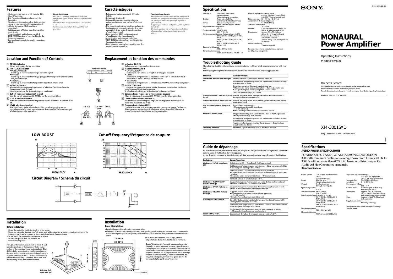
Features

- Maximum power output of 600 watts (at 4 Q).

- Class D Technology*

- This Power Amplifier is produced only for
Subwoofer.

I Direct connection can be made with the speaker
output of your car audio if it is not equipped

* Class D Technology
The Class D Technology 15 n method la convert and
ulllplify music slgunls uvth masters to high speed pulse
signals.
The uml can drive enough it speaker with Low lmpsdamc
(1 Q)

with the line output (High level input
connection).

- Built in variable LPF (Low-pass filter), and low
boost circ 't.

- Protection circuit and indicator provided.

- TEST-TONE functions of easy-checking for the
System performance.

- Two speakers terminals for parallel connections
added.

Ful'thcrmurc, ifjt'lltlll'es high efficiency and lolll hllll,
gnu-ration.

-
Location and Function of Controls

E] POWER indicator
Lights up in green during operation.
PROTECTOR indicator
' OVER CURRENT:
Lights up in red when receiving a powerful signal.
- OFFSET:
Lights up in red when the voltage going out to the Speaker terminal or the
Pin jack is too high.
' THERMAL:
Lights up in red when the temperature rises to an unsafe level.
TEST-TONE button
When the button is pressed, operations of a built-in Oscillator allow the
System conditions to check.
Hearing the tones, the System is in good conditions.
[I] Cut-off frequency adjustment control
Sets the cutoff frequency (507300 Hz) for the low7pass filters.
[3] LOW BOOST level control
Turn this control to boost the frequencies around 40 Hz to a maximum of 10
dB.
E] LEVEL adjustment control
The input level can be adjusted with this control when using source
equipment made by other manufacturers. Turn it to MAX when the output
level of the car audio seems low.

FILTER

POWER/PROTECTOR

Low BOOST LEVEL
(40sz

Caractéristiques

- Puissance de sortie maximale de 600 watts
(a 4 o).

'Technologie de classe D"

- Cet amplificateur de puissance est concu
uniquement pour un haut-parleur dext-rémes
graves.

* Technologie de classe D
La trchuuluglc dt- rlasse D est uur methods petmrtmul dz-
mnverflr cl d'lllllpliflcl' ties slguaur llluslmux grficc a des
MOSFET pour obleuit dcs slguaur pat implllsiull a
made zlifcssl',
L'nppntell pcut pilutt'l lm haul-parleur aftultle impedance

Spécifications

3-231-699-11 (2)

SONYs

- Une connexion directe est possible avec la sortie
haut-parleur de votre autoradio si celle-ci nest
pas equipée dune sortie de ligne (connexion
d/entrée haut niveau).

- Filtre passe-bas (LPF), variables et circuit
d'amplification des graves integrés.

- Avec circuit et indicateur de protection.

- TEST-TONE functions of easy-checking for the
System performance.

- Deux bornes de haut-parleurs ajoutées pour des
raccordements en parallele.

fnlhlr (l a).
Dr plus, ll l'lllpllrticlll h In gr'lltl'alioll d'lippllrrils nllzanl
Efficncllfi dr luult nil/elm cl llrlfalble degagsmnu do
clllllcw

-
Emplacement et fonction cles commandes

m lndicateur POWER
S'allume en vert en cours fonctionnement.
lndicateur PROTECTO R
' OVER CURRENT:
Sallurne en vert lors de la réception d'un signal puissant.
' OFFSET:
Sallurne en rouge lorsque la tension de sortie vers le terminal du hautz
parleur ou la prise a broches est trop élevée.
' THERMAL:
Sallume en rouge lorsque la temperature atteint un niveau trop dangereux.

Touche TEST-TO N E
Lorsque vous appuyez sur cette touche, la mise en marche d'un oscillateur
integré permet de verifier le systeme.
Si vous entendez Ie signal, le systeme est en bonne condition.
E Commandes de réglage de la fréquence de coupure
Regle la fréquence de coupure (5(L300 Hz) pour les filtres passesbas.

E Commande de niveau LOW BOOST
Tournez cette Commande pour amplifier les fréquences autour de 40 Hz
jusqu/a u.n maximum de 10 dB.

E Commande de réglage LEVEL
Le niveau dentree peut se régler avec cette Commande lors de lutilisation
d'equipements source d'autres fabricants. MetteZzle sur MAX lorsque le
niveau de sortie de linstallation audio parait faible.

LOW BOOST

dB

10

IO

FREQUENCY Hz

Circuit Diagram / Schéma du circuit

Butler

Lab 0 I>

Reno |I>

Cut

dB
IO
0

-off frequency/Fréquence de coupure

FREQ U ENCY Hz

Power

LOW BOOST

AMP

_\ I> 9]

OE)

--o

Installation

Before Installation

I Mount the unit either inside the trunk or under a seat.

- Choose the mounting location carefully so the unit will not interfere with the normal movements of the
driver and it will not be exposed to direct sunlight or hot air from the heater.

I Do not install the unit under the floor carpet, where
the heat dissipation from the unit will be
considerably impaired.

First, place the unit where you plan to install it, and
mark the positions of the four screw holes on the
surface of the mounting board (not supplied). Then
drill the holes approximately 3 millimeters (mm) in
diameter and mount the unit onto the board with the
supplied mounting screws. The supplied mounting
screws are 15 mm long. Therefore, make sure that
the mounting board is thicker than 15 mm.

264 (ID 1/2)

Uni mm (in.)
Unite : mm (po.)

-
Installation

Avant linstallation

- lnstallez lappareil dans le coffre ou sous un siege.

- Choisissez un endroit de montage judicieux pour que lappareil ne géne pas les mouvements naturels du
conducteur et pour quil ne soit pas expose aux rayons directs du soleil ou a proximité dune bouche dair
chaud.

358 (14 lul I Ninstallez pas lappareil sous le tapis, car cela

empécherait la dissipation de chaleur de lappareil.

310 (12 Va)

Tout dabord, mettez lappareil ou vous prévoyez de

linstaller et tracez les quatre trous de vis sur la surface

de la plaque de montage (non foumie). Forez ensuite les
trous selon un diametre d/environ 3 millimetres (mm) et
installez lappareil sur la plaque avec les vis de montage
fournies. Les vis de montage fournies font 15 mm de
long. Par consequent, assurez-vous que la plaque de
montage fait plus de 15 mm dépaisseur.

734 (9 VA)

D 6 (VII

Circuiterie Circuit OTL (sortie sans Plage de reglage du niveau dentree
transformateur) 0,2 - 6,0 v (prises a broche RCA)
Alimentation par irnpulsions 0,4 _ 12,0 V (entree haut niveau)

Entrees Prises a broche RCA Filtre passebas 50 - 300 Hz, -12 dB /oct
Connecteur dentrée haut niveau Amplification de basses fréquences

Sorties Bornes de haut-parleurs 0 - 10 dB (40 Hz)
Prises a broches a sortie directe Tension dalimentation

Impedance des haut-parleurs 10,5 - 16 V
1 - s n Courant a la sortie nominale: 40 A (a 4 n)

Sorties maximales 6U0 W (a 4 Q) Entree de telecorrunande: 2 mA

1200 w (a 2 9) Dimensions Approx. 358 x 50 x 264 mm
Sorties nominales (tension dalimentation a 14,4 V) (14 vs x 2 x 10 v2 po.) (l/h/p) a

300 w (20 Hz - 300 Hz, 01 °/. THD, lexclusion des parties at

a 4 o) commandes saillantes

6U0 w (20 Hz - 300 Hz, 0,6 °/. THD, Poids Approx. 35 kg (7 liv. 11 oz.) sans les

a 2 n) accessoires

1000 w (20 Hz - 300 Hz, 1,2 °/.. Accessoires fournis

THD, a 1 o) Vis de montage (4)

Reponse en freq uence
5 Hz - 300 Hz ( gdB)

Distorsion harmonique
0,06 °/u ou inferieure (a 100 Hz, 4 9)

La conception et les specifications sont sujettes a
modifications sans prcavis.

-
Troubleshooting Guide

The following checklist will assist in the correction of most problems which you may encounter with your
unit.
Before going through the checklist below, refer to the connection and operating procedures.

Problem Cause/Solution

The POWER indicator does not light The fuse is blown. a Replace the fuse with a new one.
up.

The earth lead is not securely connected. 4r Fasten the earth lead securely
to a metal point of the car.

The voltage going into the remote terminal is too low.
' The connected master unit Is not turned on. 9 Turn on the master unit.
- The system employs too many amplitiers. A Use a relay.

Check the battery voltage (10.5 - 16 V).

The OVER CURRE NY indicator light Hp Turn off the power switch. The speaker outputs are short-circuited. a
In red. Rectify the cause of the short-circuit.

The OFFSET indicator lights up in red. Turn off the power switch. Make sure the speaker lead and earth lead are
securely connected.

The THERMAL indicator lights up in The unit heats up abnormally.
red. - Use speakers with suitable impedance.
- 1 to 8 :2 (stereo).
' Make sure to place the unit in a well ventilated location.

Altemator noise is heard. The power connccting leads are installed too close to the RCA pin leads.

4r Keep the leads away from the leads.

The earth lead is not securely connected. 4r Fasten the earth lead securely
to a metal point of the car.

Negative speaker leads are touching the car chassis. 4r Keep the leads
away from the car chassis.

The sound is too low. The LEVEL adjustment control is set to the MIN position.

-
Guide de dépannage

La liste suivante vous permettra de remédier a la plupart des problemes que vous pourriez rencontrer
dans le cadre de lutilisation de votre appareil.
Avant de passer en revue la liste cizdessous, verifiez les procedures de raccordement et d'utilisation.

Probleme Cause/Solution

Lindicateur POWER ne s'allume Le fusible est grille. a Remplacez le fusible par un neuf.
pas.

Le til cle masse nest pas connecte correctement. 4r Fixez correctement le fil de
masse a un point métallique de la voiture.

La tension entrant a la borne de telecommande est trop faible.

- Lappareil maitre connecte nest pas allume. 4r Mettez lappareil rnaitre sous
tension.

- be systeme utilise trop damplificateurs, 4r Utilisez un relais.

Vérifiez la tension de la batterie (10,5 - 16 V).

Lindicateur OVER CURRENT

Coupez linterrupteur dalirnentation. Les sorties de haut-parleur sont court-
s'allume en rouge.

circuitées. 4t Remédiez a la cause du court-circuit.

Lindicateur OFFSET s'allume en Coupez linterrupteur dalimentation. Assurez-vous que le cordon de haut-
rouge. parleur et le til de masse sont correcternent branches.

L'indieateur THERM AL sallume L'appareil chauffe anormalement.
en rouge. - Utilisez des haut-parleurs dune impedance appropriée.
- 1 a s a (stereo).
. Installez lappareil dans un endroit bien aere.

Lalternateur émet un bruit. Les cables dalimentation sont installés trop pres des cables a broches RCA.

4r Eloignez les cables lun de lautre.

Le til de masse nest pas connectc correctement. 4r Fixcz correctement le fil de
masse a un point metallique de la voiture.

Les fils négatifs des haut-parleurs touchent la carrosserie de la voiture.
a Eloignez les fils de la carrosseric de la voiture.

Le son est trap faible- La commande de reglage de niveau est mise en position MIN.

MONAURAL
Power Amplifier

Operating Instructions
Mode demploi

Owner's Record

The model and serial numbers are located on the bottom of the unit.
Record the serial number in the space provided below.
Refer to these numbers whenever you call upon your Sony dealer regarding this product.

Model No. XM-30015XD Serial No-

XM -30015XD

Sony Corporation @2001 Primed ll'l Korea

-
Specifications

AUDIO POWER SPECIFICATIONS

POWER OUTPUT AND TOTAL HARMONIC DISTORTION

300 watts minimum continuous average power into 4 ohms, 20 Hz to
300 Hz with no more than 0.2% total harmonic distortion per Car
Audio Ad Hoc Committee standards.

Other Specifications

Circuit system on (output transformerless) input level adjustment range

circuit 0.2 - 6.0 V (RCA pin jacks)

Pulse power supply 04 a 12.0 V (High level input)
Inputs RCA pin jacks Low-pass filter 50 - 300 Hz, -12 dB /oct

High level input connector Low boost 0 - 10 dB (40 Hz)
Outputs speaker terminals Power supply voltage

Through out pin jacks 10.5 - 15 V

speaker impedance Current drain at rated output: 40 A (at 4 o)

1 _ 8 :2 Remote input: 2 mA

Maximum outputs 600 w (at 4 9) Dimensions Approx. 358 x 50 x 264 mm
12llOW(atZQ) (14/s><1Ll/2 In) (w/h/d) not
Rated outputs (supply voltage at 14.4 V) incl. projecting parts and controls
300 w (20 Hz - 300 Hz, 0.2 /0 Mass Approx. 3.5 kg (7 lb. 11 oz.) not
THD, at 4 :2) incl. accessories
600 w (20 Hz - 300 Hz, 0.6 "/a Supplied accessories
THD, at 2 9) Mounting screws (4)
1000 w (20 Hz - 300 Hz, 1.2 %
THD, at 1 9) Design and specifications are subject to change

Frequency response without notice.
5 Hz - 300 Hz (fidB)
Harmonic distortion

0.06 °/. or less (at 100 Hz, 4 n)

Page 2

Connections

Caution

I Before making any connections, disconnect
the earth terminal of the car battery to avoid
short circuits.

- Be sure to use speakers with an adequate
power rating. If you use small capacity
speakers, they may be damaged.

- Do not connect the (3 terminal of the speaker
system to the car chassis.

- Install the input and output leads away from
the power supply lead as running them close
together can generate some interference noise.

- This unit is a high powered amplifier.
Therefore, it may not perform to its full
potential it used with the speaker leads
supplied with the car.

- If your car is equipped with a computer
system for navigation or some other purpose,
do not to remove the earth wire from the car
battery. It you disconnect the wire, the
computer memory may be erased. To avoid
short circuits when making connections,
disconnect the +12 V power supply lead until
all the other leads have been connected.

Make the terminal
connections as illustrated below.

Connexions
Attention

Avant d/effectuer les Connexions, débranchez
la borne de masse de la batterie de voiture
pour eviter tout courtscircuit.

0 Veillez a utiliser des hautsparleurs de
puissance adequate. Si vous utilisez des haute

parleurs de faible capacite, ils risquent détre
endommages.

Ne raccordez pas la borne @ du systeme du
hautsparleur a la carrosserie du véhicule.
Eloignez les cables d/entrée et de sortie du
cable dalimentation pour éviter les
interferences.

Cet appareil est un amplificateur de haute

o

o

o

puissance. ll ne peut donc deployer sa pleine
puissance que si les cables de hautsparleurs de
la voiture lui sont raccordes.

Si votre voiture est equipée d'un systeme de
navigation ou dun ordinateur de bord, ne
retirez pas le fil de terre de la batterie de la
voiture, sinon les données mémorisées seront

o

etfacées. Four éviter un courtscircuit lorsque
vous effectuez les branchements, branchez le
cable dalimentation +12 V apres avoir
branché tous les autres f s.

Effectuez les oonnexions de la
maniére illustrée ci-dessous.

N ote

When you tighten the screw, as careful not to
apply too much torqlar as doillx so may damage
the screw.

* The torque value should be less than 1 N'ltl.

Remarq ue
Ne serrez pas la vis selon an couple" tropfort car nous
pourriez l'clldommdxer.

s La oaleur du couple de scrrllxe doit etre inferteure a 1
NI m.

Power Connection Leads
Cables d'alimentation

779 Fuse (80 A)

Fusible (80 A)

+12 V car battery
Batterie de voiture +12 V

to a metal point of the car b all

vers une partie métallique
de la carrosserie

terminal (REMOTE) to the accessory porller supply,

* lfyou trace the factory original or sonic other car audio ioitliout a remote output on the atllpllflcr, collllcct the remote input

* Si vous drsposez dti nlodele d'ol'igille an d'un autre autaradia dont l'aniplitieateur iie eaniporte pas de sortie de
telecoiuiuande, raccordez la porne d'clltree de teleconirnande (REMOTE) a la prise d'alimentatlorl accessoires.

Remote output *
Sortie dc
téIECommmlde *
(REM OUT)

Car audio
Autoradio

Notes on the pow er supply

- Connect the +12 v power supply lead only after all the
other leads have been connected

I Be sure to connect the earth lead of the unit
securely to a metal point of the car. A loose
connection may cause a malfunction of the
ampli er.

I Be sure to connect the remote control lead of the car audio
to the remote terminal,

- When using a car audio without a remote output on Iho
anipli/ier, connect the remote input terrninal (REMOTE)
to the accessory power supply.

- use the power supply lead unth a fuse attached (so A).

- Place the fuse in the power supply lead as close as possible
to the car battery.

0 Make sure that the leads to be connected to the +12 V and
GND terrrlmals of this unit respectiocly must he larger
than 4-Gauge (AWC-4) or with the sectional area ofnlore
tllall 22 mm).

Remarques sur lalimentation électrique

I Raccordez le cable d'alirnentatlml +12 V untqucmellt
apres avoir realise toutes les autres Connexions.

o Raccordez correctement le fil de masse a une
partie métallique de la voiture. Une connexion
lache peut provoquer un dysfonctionnement de
lamplificateur.

0 Velllcz ti raccorder lefil dc ttltcorrlrnande de l'aulomdio a
In home de teIecornrnande.

- Si vous utilise: iin autoradio dant lauiplifteateur ne
coinporte pas de sortle de teleconnnande, raccordcz la
borne d'entrée de la telecomnlarlde (REMOTE) fl la prise
dnlimetltlltl'orl accessoires.

0 Utilisez ml edlllc d'allrrlerltatiou mum d'llnfusihlc (80 A),

. riuez le calile d'alirricntatian le plus pres possililo de la
batterie de voiture.

I Volts devcz raceordcr des cables de eallbre superieurs a 4
iAWC-4) ou d'lme section sllperlcllre a 22 mm2 aux
homes +12V et GND.

If the unit is connected to one Subwoofer
Si l'appareil est raccordé a un caisson de basses.

Car audio
Autoradio

LINE 0UT*

Subwoofer (min. TOTAL 1 Q)
Caisson de grave (min. TOTAL 1 9)

Pour plus dc details stir les réxlages des eanirruitateurs
et coimnartdes, roportoz-sious a htltpldrettlent el
folletloll des corninandes '

For details on the settings ofsrilltches and controls,
refer to Location and Function ofContmls.
t - you can connect either output terminal. s - [eu importe la porne de sortie ane mus raccordez,

- The minimum resistance must he] Q in total, - La reslstance nlillmtalc doit etrc egale a 1 Q 11 total.

If the unit is connected to two Subwoofers
Si l'appareil est raccordé a deux caissons de basses

Car audio
Autoradio

LINE OUT"

SubwooferM SubwooferM
(min. TOTAL 2 9) (min. TOTAL 2 Q)
Caison de graveM
(min. TOTAL 2 o)

(min. TOTAL 2 9)

For details on Ihe sottinps ofsrllltclles and controls, refer to Pour plus de details stir les réglages des eaniniutateurs
Location and Function ofCoiitrols," et coininandcs, reportea-oous a "Elllplacement cl

. . anction des corniriandes"
* - You can connect other output terminal. f

- The ininiininu resistance inust he] (2 in total, * - leu iniporte la porne de sortie aue vous raccorde:
is When you use two terminals with speakers, each of - La reslstatlce rrlillimalc doit etre egnle a 1 9 an total.
terminal resistance is 2 Q at a iiunnnuin H Lorsaue sous utilise: deux pornes aoec des halit-
(Troo terminals are connected onth each other in the unit.) parlenrs, la resistance de chaane porne doit au nioins
etre exalt» a z :2
(Les dell): liornes sont raccordecs tune a l'alltre dans
l'appareil l

Two output channels (THROUGH OUTPUT)
Duex canaux de sortie (THROUGH OUTPUT)

Car audio
Autoradio

LINE OUT

INPUT THROUGH OUT INPUT
-sszTPtHHH 7-:3'FYT-tHi-tl-l we?
8@
@

Lll 88 eaglflfllos sold

:0

Subwoofer (min. TOTAL 1 Q)
Caisson de grave (min. TOTAL 1 Q)

* When you connect amplifiers using with
the THROUGH OUT pin jacks, it allows
you to connect up to a maximum of three.

* Lorsque vous raccordez des amplificateurs a
laide des prises a broches THROUGH OUT,
vous pouvez raccorder jusqu/a 3 amplificateurs

Otherwise the necessary output levels can au maximum.

not be obtained, and your car audio may be Sinon les niveaux de sortie requis ne peuvent

damaged. pas etre obtenus et votre autoradio risque
d'étre endommage.

Use the THROUGH OUT terminal when

you install more amplifiers. The signals are

output as they were input. (LOW BOOST,

LFF do not work.)

Utilisez la borne THROUGH OUT lorsque
vous installez plusieurs ampliticateurs.
Les signaux sont sortis comme ils sont
entrés. (LOW BOOST, LPF ne
fonctionnent pas.)

Caisson de grave

If the units are in stereo playback mode
(Playing back in stereo mode requires two units.)

Si les appareils sont en mode de lecture stéréo
(La lecture en mode stéréo requiert deux appareils.)

Car audio
Autoradio

LINE our*

Left channel
Canal gauche

Right channel
Canal droit

Right subw oofer
(min. TOTAL 1 Q)
Caisson de grave droit
(min. TOTAL 1 Q)

Left subwoofer (min. TOTAL 1 D.)
Caisson de grave gauche (min. TOTAL 1 9)

For details on the settings ofsrllltches and controls,
refer to Location and Function ofControls."

Pour plus de details snr les re'glaxes des corniiiutateurs

et colllnlandes, report c-volls a Eriiplacerrterit et

folletlon des coiinuandes".

* - you can connect either out ut terniinal. .
V t - ecu nnporte to home de sortie aue oous raccordez.

-rlie niiniiuuiu resistance must he] din total. , , , . , , .
- La resistance iiiinirnale dolt etre (tale a 1 52 au total.

High Level Input Connection

(As a Monaural Amplifier for a Subwoofer)

Connexion d'entrée a haut niveau

(Comme amplificateur monauml pour un haut-parleur dextrémes
graves)

Left speaker
Haut-parleur gauche


Car audio

Autoradio
Right speaker

Haut-parleur droit

Input lead (Not supplied)
cable dentrée (Non fournis)

Subwoofer

(min. TOTAL 1 9.)
Caisson de grave
(min. TOTAL 1 9.)

Pour plus de details sur les regldges des counnutatenrs
us a Emplacemcrll et

For details on the settings ofsroitelles and controls,
ref/Jr to "Location and Function ofCoIttloIs (I Command, PW?

forlction des conlrnan

Speaker lead direct in connector

Cordon de haut-parleur directement dans le connecteur

as 1 Left speaker

Haut-parleur gauche

Rig ht spea ker

Car audio
Autoradio

Haut-parleur droit

White Grey
Blanc Gris

Slack-striped lead
Cordon raye' noir

on
on
on
0U

,/

Flat-head screwdriver

Lead diameter 0.3 - 1.25 mm (AWG 22 - 16)
Section du cordon : 0,3 - 1,25 mm (AWG 22-16)

Toumevis a lame plate

11 (7/15)

Unit ' mm (in.)
Unite : mm (po.)

Precaution

- This unit is dagned for negative earth 12 V DC
operation only.

- Usespeakers with suitable impedance.

- 1 to 8 52.

- Do not connect any active speakers (with bui It-in
amplifiers) to thespeaker terminals of the unit
Doing so may damage the active speakers

- Avoid installing the unit where:
~ it would be subjectto high temperaturs such

as from direct sunlight or hot air from the
heater
- itwould be aposed to rain or moisture
A it would be subjectto dust or dirt.

- If your car is parked in direct sunlight and there
is a considerable rise in temperature inside the
car, allow the unit to cool down before use.

- When installing the unit horizontally, besure not
to cover the fins with the floor carpet etc.

- If this unit is placed too closeto thecar radio,
interference may occu rt In this case, relocate the
amplifier away from the car radio

- If no power is being supplied to the master unit,
check the connecti ons.

- This power amplifier employs a protection
ci rcuit* to pretext the transistors and speakers if
the amplifier malfunctions. Do not attempt to tst
the protection circuis by covering the heat sink
or connecting improper loads.

- Do not use theunit on a weak battery as its
optimum performance depends on a good power
su pplyi

- For safety reasons, keep your car audio volume
moderateso that you can still hear sounds
outside your car.

Fuse Replacement

If the fuse blows, check the power connection and
replace the fuse. If the fuse blows again after
replacement, there may be an internal malfuncli on.
In such a case, consult your nearst Sony daler.

Warning

When replacing the fuse, be sure to use one
matching the amperage stated above the fuse
holder. N ever use a fuse with an amperage rating
acceding theone supplied with the unit as this
could damagethe uniti

*Protection circuit
This amplifier is provided with a protection circuit that
operates in the following cases.-
s when the unit is overheated
7 when a DC current is generated
- when the speaker terminals are sllort circuitcd.
l'hc PROTECTOR indicator lixlits llp ill red and the unit
will shut dololl.
[flhls happens, turn offthe connected equipment, talte out
the cassette tape or disc, and dcterrnme the cause of the
malfunction, lfthe amplifier has overheated, wait until the
unit cools down before use.

If you have any qustions or problems concerning
your unit that are not covered in this manual,
please consult your nearst Sony dealer.

Précautions

- Cet appareil 5t concu pour fonctionner sur du
cou rant conti nu 12 V a masse negative.

- utilise d5 haut-parleursdune impedance
appropriée.

# 1 a 8 52

- N e racoorda pas de haut-parleurs actifs (avec
ampl ificateurs intégré) aux horns de haut-
parleurs de cet appareil. Cette operation pourrait
endommager Is haut-parleurs actifs.

- Evita dinstaller | 'appareil 5 d6 endroits ou:

- i| serait yposéa d$températurs élevés,
comme sous Is rayons direcs du soleil ou a
proximitédune bouche d'air chaud;

-- il serait yposéa Ia pluie ou a I'humidité;

- i| serait 9

- Si votre voiture a garéeen plein soleil et que la
températureé Iintérieur de Ihabitacle a
considérablement augmenté, Iaissa refroidir
Iappareil avant delutiliser.

- Lorsquevous installa I'appareil a I'horizontale,
veilla a ne pas recouvrir Ia grilledaé'ation avec
letapis, etc.

- Si cet appareil sttrop prs de I'autoradio, i| 5t
possible qu'il y ait d5 interférencs. Dans ce cas,
éloigna Iamplificateur de | 'autoradioi

- Si I'appareil principal nst pas alimenté, vérifiez
Is connexions

- Cet amplificateur de puissance utilise un circuit
de protection* visant a protéger I5 transi stors et
I5 hautsparleurs en cas dedysfonctionnement de
Iamplificateur. N etenta pas detster Is
circuits de protection en couvrant Iaccumulateur
de dwaleur ou en branchant d5 chargs
inadéquata

- N 'utilisa pas cet appareil avec une batterie
fai ble car Is performancs optimals de
Iappareil dependent dune bonne alimentation
électrique.

- Pour d5 raisons desécurité, garda Ie volumede
votre i nstallation audio devoiturea un niveau
permettant encore Ia perception d5 bruits
extérieurs.

Remplacement du fusible

Si lefusible grille, vérifia Ia connexion électrique
et remplacez lefusi bl e. Si lefusible grille encore
apré ce remplacement, ii at possible qu'il y ait un
dysfoncli onnement interne. Dans ce cos, ad rascz-
vous a votre distributeur Sony la plus proche

Avertissement

Lorsdu remplacementdu fusible, veilla a
rspecter Iampérage indiqué au-dfius du
logement du fusible. N 'utilisa jamais un fusible
d'ampérage supérieur a celui fourni avec
Iappareil, car cela pourrait endommager
Iappareil.

6 Circuit de protection
Cet aniplifieateur est equipe d'un circuit de protection ain
s'aetive dalls les ens suit/ants:
_ en cas de slllellauflc de l'appareil
7 en cas de generation d'un couraitt contmu
e lorsque les homes de liaut-parleurs sont court-
circuittes
L'indteatclll' PROTECTOR s'alllline en lflttxi' et
l'appareil s'arrete.
Dans cc cas, eteignez tout oaiiipeinent raeeorde, retirez la
cassette ou le disque et detel'nlillez hi cause (In
dysfonctionnornent. si l'arnplifieateur a surcliauffe',
attcndez euc lappareil refrordlsse avdllt de le Telltiliser.

Si vous ava d5 qustions ou d5 problem$
concernant votre appareil qui ne sont pas abordé
dans ce mode demploi, ad rssasvous a votre
distributeur Sony Ie plus proche.