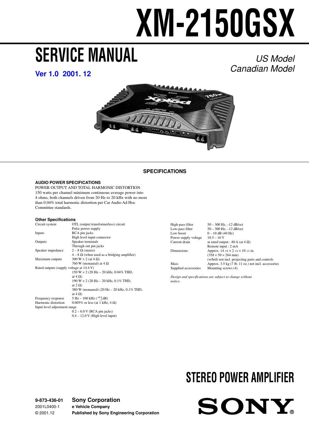
Sony xm 2150gsx car amplifier

This is the 22 pages manual for sony xm 2150gsx car amplifier.
Read or download the pdf for free. If you want to contribute, please mail your pdfs to info@audioservicemanuals.com.

Page: 1 / 22
left right
sony xm 2150gsx car amplifier

Extracted text from sony xm 2150gsx car amplifier (Ocr-read)


Page 2

XM-215OGSX

Note for Replacement of FET

Change the both channels of FETs at the output stage.

If one or both parts in the following combination is broken, the
service kit should be ordered.

Service kit part No.
0108, 112
0208 212 XA33817586»1
0109, 113
0209 213 X-3381A587-1

Notes on Chip Component Replacement

0 Never reuse a disconnected chip component.

I Notice that the minus side of a tantalum capacitor may be dam-
aged by heat.

SAFETY-RELATED COMPONENT WARNING !!

COMPONENTS IDENTIFIED BY MARK A OR DOTTED LINE
WITH MARK A ON THE SCHEMATIC DIAGRAMS AND IN
THE PARTS LIST ARE CRITICAL TO SAFE OPERATION.
REPLACE THESE COMPONENTS WITH SONY PARTS WHOSE
PART NUMBERS APPEAR AS SHOWN IN THIS MANUAL OR
IN SUPPLEMENTS PUBLISHED BY SONY.

ATTENTION AU COMPOSANT AYANT RAPPORT
A LA SECURITE!!

LES COMPOSANTS IDENTIFIES PAR UNE MARQUE A SUR LES
DIAGRAMMES SCHEMATIOUES ET LA LISTE DES PIECES
SONT CRITIQUES POUR LASECURITE DE FONCTIONNEMENT.
NE REMPLACER CES COMPOSANTS QUE PAR DES PIECES
SONY DONT LES NUMEROS SONT DONNES DANS CE MANUEL
OU DANS LES SUPPLEMENTS PUBLIES PAR SONY.

2

TABLE OF CONTENTS

1 . G EN ERAL
Location and Function of Controls
Connections ..............................

2. DISASSEMBLY

2.1_ Bottom Plate .. 6
272. Main Board 6
273. Front Panel . 7
2-4. Led Board 7
3. ELECTRICAL ADJUSTMENT ...................................... 8

4. DIAGRAMS

4-1. Block Diagram .....
4.2 Schematic Diagram iMain Section (1/2)7
473. Schematic Diagram iMain Section (2/2)7
4-4. Printed Wiring Boards iMain Sectioni

5. EXPLODED VIEWS
51. Heat Sink Section
5-2. Main Board Section

.14

.15

6. ELECTRICAL PARTS LIST ........................................ l6