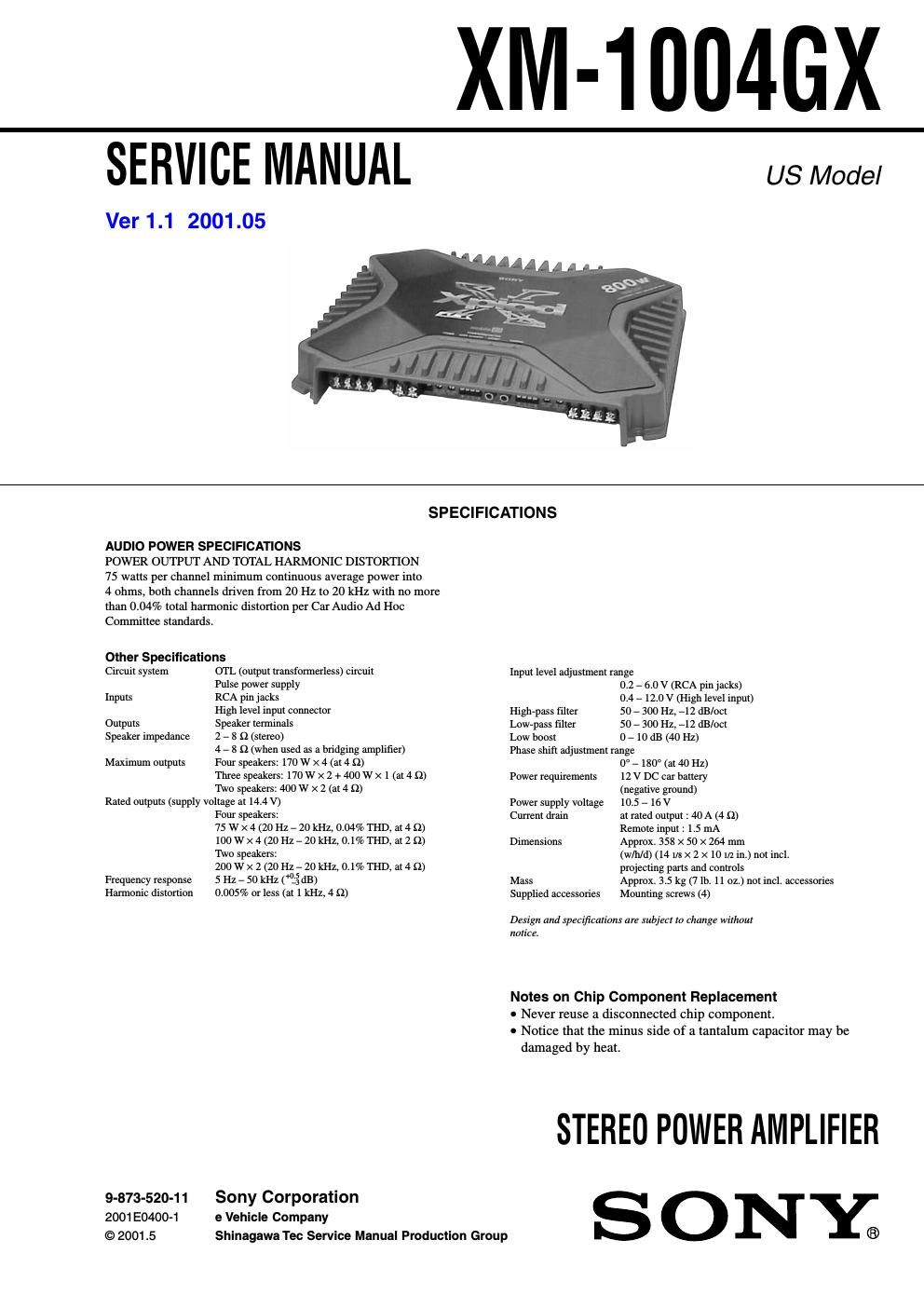
Sony xm 1004 gx service manual

This is the 28 pages manual for sony xm 1004 gx service manual.
Read or download the pdf for free. If you want to contribute, please mail your pdfs to info@audioservicemanuals.com.

Page: 1 / 28
left right
sony xm 1004 gx service manual

Extracted text from sony xm 1004 gx service manual (Ocr-read)


Page 1

2 TABLE OF CONTENTS 1. GENERAL Location and Function of Controls .......................................... 3 Connections ............................................................................. 4 2. DISASSEMBLY 2-1. Plate, Bottom ....................................................................... 6 2-2. AMP Board Section ............................................................. 6 2-3. AMP Board, Filter (A) Board, Filter (B) Board .................. 7 2-4. LED Board ........................................................................... 7 3. ELECTRICAL ADJUSTMENT ...................................... 8 4. DIAGRAMS 4-1. Block Diagram ..................................................................... 9 4-2. Printed Wiring Board -“AMP Section-“.............................. 11 4-3. Schematic Diagram -“AMP Section (1/2)-“........................ 12 4-4. Schematic Diagram -“AMP Section (2/2)-“........................ 13 4-5. Schematic Diagram -“Filter (A), Filter (B), LED Section-“.................................................................... 14 4-6. Printed Wiring Boards -“Filter (A), Filter (B), LED Section-“.................................................................... 15 5. EXPLODED VIEWS 5-1. Heat Sink (Main) Section .................................................. 17 5-2. AMP Board Section ........................................................... 18 6. ELECTRICAL PARTS LIST ........................................ 19 XM-1004GX SAFETY-RELATED COMPONENT WARNING!! COMPONENTS IDENTIFIED BY MARK 0 OR DOTTED LINE WITH MARK 0 ON THE SCHEMATIC DIAGRAMS AND IN THE PARTS LIST ARE CRITICAL TO SAFE OPERATION. REPLACE THESE COMPONENTS WITH SONY PARTS WHOSE PART NUMBERS APPEAR AS SHOWN IN THIS MANUAL OR IN SUPPLEMENTS PUBLISHED BY SONY.

Page 2

3 XM-1004GX SECTION 1 GENERAL This section is extracted from instruction manual. LEVEL HPF OFF LPF Phase shift NormalAMP Power Lch LEVEL HPF OFF LPF InvertedAMP Power Rch BTL. Lch Rch(BTL.) FILTER FILTER LOW BOOST LOW BOOST TEST TONE Phase shift 10 10 0 40 100 1k 10 0 -10 -20 -30 -40 -50 -60 -70 -80 10 100 1k HIGH PASS 50Hz 150Hz300Hz 50Hz LOW PASS 150Hz300Hz FILTER LPF OFF HPF LEVEL LOW BOOST (40Hz) MIN MAX 0dB +10dB50Hz 300Hz 0Ëš180ËšPHASE TEST TONE POWER/PROTECTOROVER CURRENT POWER OFFSET THERMAL Location and Function of Controls 1POWER indicator Lights up in green during operation. 2PROTECTOR indicator -OVER CURRENT: Lights up in red when receiving a powerful signal. -OFFSET: Lights up in red when the voltage going out to the Speaker terminal or the Pin Jack is too high. -THERMAL: Lights up in red when the temperature rises to an unsafe level. 3TEST-TONE button When the button is pressed, operations of a built-in Oscillator allow the System conditions to check. Hearing the tones, the System is in good conditions. 4FILTER selector switch When the switch is in the LPF position, the filter is set to low-pass. When in the HPF position, the filter is set to high-pass. 5Cut-off frequency adjustment control Sets the cut-off frequency (50-“300 Hz) for the low-pass or high-pass filters. 6PHASE SHIFT ADJUSTMENT control Adjusting a phase shift for Subwoofer driving by using the knob, comes true a controlled rich bass playback preventing by interference from Full range speakers. 7LOW BOOST level control Turn this control to boost the frequencies around 40 Hz to a maximum of 10 dB. 8LEVEL adjustment control The input level can be adjusted with this control when using source equipment made by other manufacturers. Turn it to MAX when the output level of the car audio seems low. Emplacement et fonction des commandes 1Indicateur POWER Sallume en vert en cours fonctionnement. 2Indicateur PROTECTOR -OVER CURRENT: Sallume en vert lors de la rĂ©ception dun signal puissant. -OFFSET: Sallume en rouge lorsque la tension de sortie vers le terminal du haut- parleur ou la prise Ă  broches est trop Ă©levĂ©e. -THERMAL: Sallume en rouge lorsque la tempĂ©rature atteint un niveau trop dangereux. 3Touche TEST-TONE Lorsque vous appuyez sur cette touche, la mise en marche dun oscillateur intĂ©grĂ© permet de vĂ©rifier le système. Si vous entendez le signal, le système est en bonne condition. 4SĂ©lecteur FILTER Lorsque le commutateur est en position LPF, le filtre est mis sur passe-bas. Lorsquil est en position HPF, le filtre est mis sur passe-haut. 5Commandes de rĂ©glage de la frĂ©quence de coupure Règle la frĂ©quence de coupure (50-“300 Hz) des filtres passe-bas ou passe-haut. 6Commande PHASE SHIFT ADJUSTMENT RĂ©glez le dĂ©phasage du Subwoofer Ă  laide du bouton afin dobtenir une restitution fidèle des frĂ©quences graves en Ă©vitant les interfĂ©rences avec les frĂ©quences Ă©mises par les haut-parleurs principaux. 7Commande de niveau LOW BOOST Tournez cette commande pour amplifier les frĂ©quences autour de 40 Hz Ă  un maximum de 10 dB. 8Commande de rĂ©glage LEVEL Le niveau dentrĂ©e peut se rĂ©gler avec cette commande lors de lutilisation dĂ©quipements source dautres fabricants. Mettez-le sur MAX lorsque le niveau de sortie de linstallation audio paraĂ®t faible. Circuit Diagram / SchĂ©me du circuit LOW BOOST dB FREQUENCY Hz FREQUENCY Hz dB Cut-off frequency/FrĂ©quence de coupure 20 0 -20 -40 -60 -80 -100 -120 -140 -160 10 100 1k 10k -180 -200 0Ăź 180Ăź Position of knobs Position des boutons FREQUENCY Hz deg PHASE SHIFT Front : Avant : Rear : same as Front Arrière : identique Ă  lavant