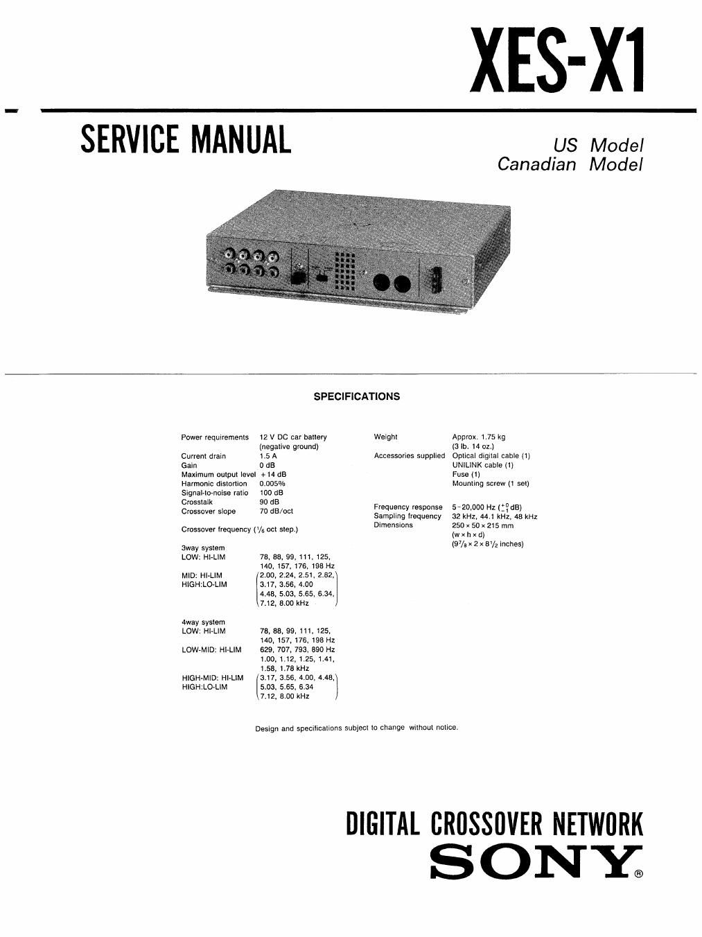
Sony xes x 1 service manual

This is the 26 pages manual for sony xes x 1 service manual.
Read or download the pdf for free. If you want to contribute, please mail your pdfs to info@audioservicemanuals.com.

Page: 1 / 26
left right
sony xes x 1 service manual

Extracted text from sony xes x 1 service manual (Ocr-read)


Page 1

XES-XI

SERVICE MANUAL us Model

Canadian Model

SPECIFICATIONS

Power requirements 12 V DC car ballery Weight Approx. 1.75 kg

(negative ground) (3 lb. 14 01.)
Current drain 1.5 A Accessories supplied Oplical digilaI cable (1)
Gain 0 dB UNILINK cable (1)
Maximum oulput level +14 dB Fuse (1)
Harmonic disIonion 0.005% Mounting screw (1 set)
signal-lovnoise rario 100 dB
Crosstalk 90 dB 7 7
Crossover slope 7° dB/ocl Frequency response 5 20,000 Hz (_' dB)

Sampling frequency 32 kHz. 441 kHl. 48 kHz

Crossover Irequency (V. ocl slep.) Dvmensrons (25: Riot"; 215 mm
Sway SYSISITI (97/; x 2 x 5V2 inches)
LOW: HI-LIM 73, 33, 99, 11, 125,

140, 157, 176, 196 Hz
MIDI HI>LIM 2.00, 2.24, 2.51. 2.52,
HIGHZLO'LIM 3.17, 3.56, 4.00

4.48. 5103, 5.55. 6.34,

7,12, 5,00 11

«way system

LOW: HI-LIM 78, 88, 99. 111. 125.
140. 157, 176, 198 HZ

LOW-MID: HI-LIM 629. 707. 793, 890 Hz
1.00.1.12. 1.25.1441,

1.58, 1.78 kHz
HIGH-MID: HlelM 3.17, 3.56, 4.00, 4.48,
HIGHILO-LIM 5.03, 5.65. 6.34

7.12, 8.00 kHz

Design and specificalions subject lo change wilhoul no|ice.

DIGITAL cnossnvrn NETWORK
S ON Y.

Page 2

XES- X1

Features TABLE or: CONTENTS

Section Title Page
The XES-Xi is a Digital Crossover Network 1. GENERAL ---------------------------------- 3

used in multi-ampliiisr systems. This unit

divides digital sound signals by each frequency

and outputs analog signals. Dividing digital 2. UNILINK ----------------------------------
sound signals maintains high quality sound.

- You can control the sound elleots by remote 3. DIAGRAMS
commander supplied with XES-Pl. ,

- FIR filter' makes straight phase. and 3'1- 1C Description """"""""""""""""" 7
decreases phase shift at each frequency 3_2. IC Block Diagrams ............................. 9
band.

- You can adjust lime-alignment tor each 3-3. Semiconductor Lead Layouts ----------------- 12
speaker unit. _ - ................................

- You can select 3 way or 4 way speaker 3 4' BIOCk Diagram 13
system. 3-5. Printed Wiring Board - Digital Section - 16

3-6. Schematic Diagram - Digital Section - - - ~ ~ ~ 17

" FIR (Finite Impulse Response) . . .

Usual iilter begins to roll phase, but FIR filter 3'7 SChematC Dagam Anabg SW10 23
makes Phase Sl'aigm i" PrinCiP'e- 3-8. Printed Wiring Board - Analog Section - ~ - ~ 27

" Time-alignment
Time-alignmenl decreases band signal in ................... . .......
each range 0~10 m sec STEP 0.1 m sec. 4' EXPLODED VIEWS 30
Calculaling into distance, it is 0-3.4 m STEP
8.4 cm. And it keeps away speaker lrorn a
listener.
Thus this iunction enables the listener to
hear the sound from all speakers as it at the
same distance.

5. ELECTRICAL PAnTs LIsT -------------------------- 31

Operating the unit separately
1. Conect the power supply to the UNILINK
terminal (XES-Pl or DISPLAY).

Notes on chip component replacement 2. Short E-C of Q503 on the [ANALOG BOARD].
0 Never reuse a disconnected chip component.
0 Notice that the minus side of a tantalum capacitor may PLUG. CONNECTOR.(UNIL|NK)
be damaged by heat.
< 'NSIDE + B (10.5~16V)
VIEW

- B (0V)

[ANALOG BOARD]

W4 L500
cm 302