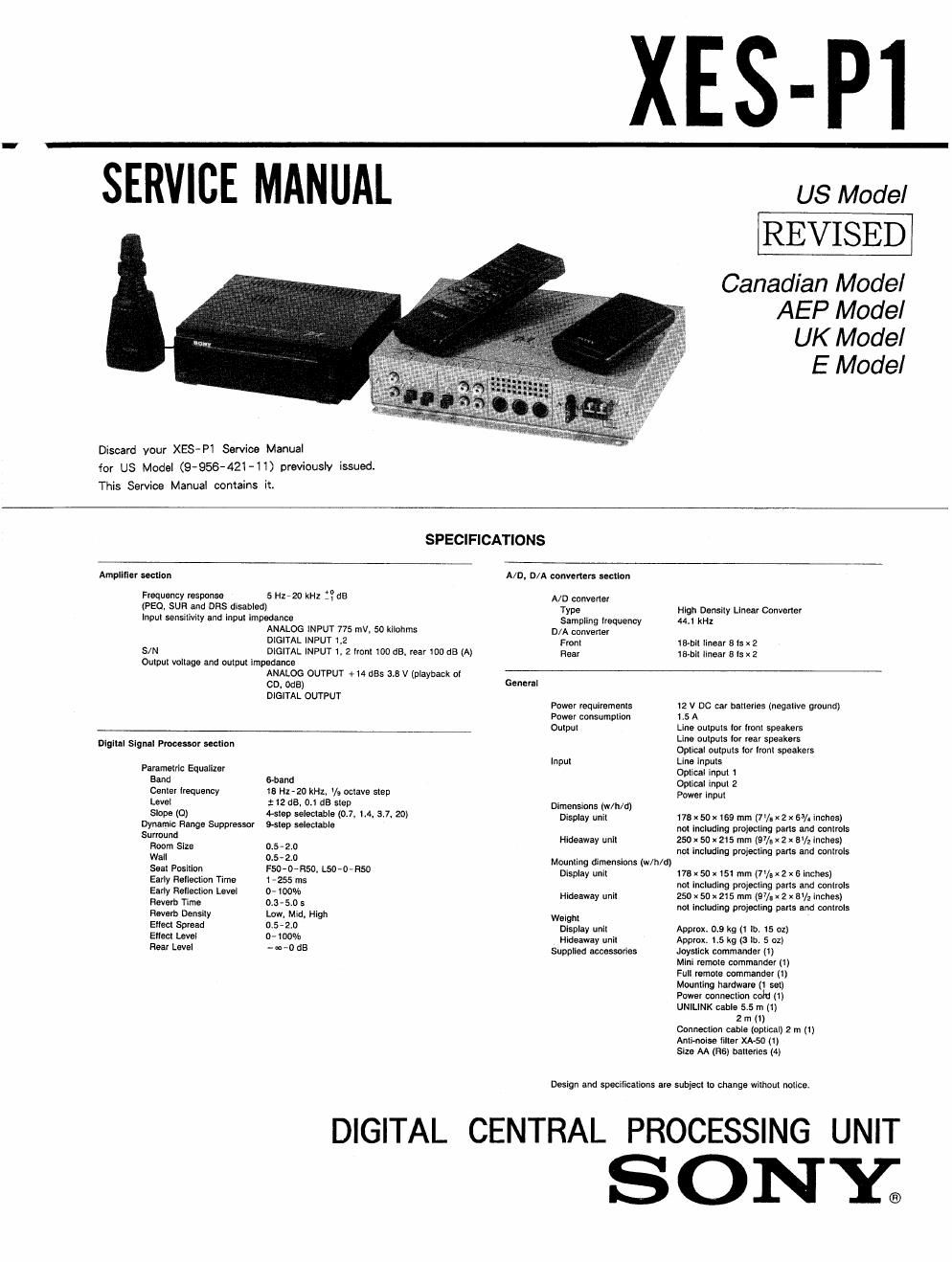
Sony xes p 1 service manual

This is the 90 pages manual for sony xes p 1 service manual.
Read or download the pdf for free. If you want to contribute, please mail your pdfs to info@audioservicemanuals.com.

Page: 1 / 90
left right
sony xes p 1 service manual

Extracted text from sony xes p 1 service manual (Ocr-read)


Page 1

XES-PI

SERVICE MANUAL

Discard your XES-P1 Service Manual

for US Model (9'956-421-11) previoust issued.
This Service Manual contains it.

US Model

REVISED

Canadian Model
AEP Model

UK Model

E Model

SPECIFICATIONS

Amplmev soouon

Frequency response

5 H1720 kHz flea

A/D, D/A convarlar: mlIun

A/ D converter

(PEG. sun and ons disabled) Type HIgn canslly LInaar Convener
InpuI sansilivily and inpul lmpedanca Sampling lrsquency 1 kHz
ANALOG INPUT 775 mv, so kiIonrns D/A convener
DIGITAL INPUT 1,2 From 18-h IInaar a la k 2
S/N DIGITAL INPUT 1. 2 lronl 100 dB, rear 100 dB (A) near mail linear a Is x 2
DulpuI vollage and ouiprrl impedance
ANALOG OUTPUT +14 685 3.8 v (playback o1
CD. one) General
DIGITAL OUTPUT . .
Power requiramanls 12 v DC car hallenes (nsgallve ground)
Power consumpIiori 1.5 A
Oquul Line uulpuls lor Ironl speakers
Line oulpuls Ior rear speakers
"9"" 59"" Pmmr 1' OpIical ourpuls lor lronl speakers
lnpuI Line lnpuls
Paramelrlc Equalizer Oplical lnpul 1

Bend 6-band OpIicai inpuI 2

Cenler Irequency is Hz~20 kHz, Vg ocIave slep Power inpul

Level 1 ta as, all da slep Dimensions (mm)

Slave (0) Mien selemable (0.7, 1.4. 3.7. 20) Display unil 178 x 50 x I69 mm (71/. x 2 x 5% inches)
Dynamic Range Suwessav wisp saleclable not includlng prcIeclIng pans and eonlrols
Surround Hideaway unii 250 x 50 x 215 mm (97/5 x 2 x lavZ inches)

Room Size 0.5-2.0 nm including projeciing pans and canlrols

W3" 05*240 Mourning dimensiona (w/h/d)

59-1 vanion FEW-5% 9-0450 Dlsplay null 175 k so )1 151 mm (71/. x 2 x 6 inches)

Eally Hellenic" Time 1 -255 ms nol |Mludlng prnieeIing pans and oonlrols

Early Ransom" Level 0* 30% Hideaway uni| 250 x 50 x 215 mm (97/. x z x av, Inches)

Revert: Time 0.3-5.0 s nol Including prpiacimg pans and tunnels

Raverh DensIIy Low. Mid, High Weigh.

EIleci Spread 0-5-10 Display unil Approx. 0.9 kg (1 lb. 15 oz)

Ellecl Level 0-00% Hideaway unII Approx. 1.5 kg (5 lb. 5 02)

Flea! Level - m -0 dB Supplied accessorles Joyslick commander (1)

DIGITAL

Mini mmoia commander (1)
Full remole commander (1)
Mourning hardware (1 sel)
Power connecIion cqu (1)
UNILINK cable 5.5 m (1)

2 m (1)
Conneclion cabIa (oplical) 2 m (l)
Anlinolse lilier XA-so (1)
Size M (He) ballenes (4)

Design and specmeaflons are subject lo change wiInoul notlce.

CENTRAL PROCESSING UNIT

SONY;

Page 2

Factory Preset Parameters

Features

- Use at Dlgllal Signal Pmoemr lose) lo lreely
conlrol the acoustics inside your car (page as)

A B-band Parametric Equalizer (no) allowan
you [0 Iinely adiusr sound quality (page 56)

, ~Use oi Dynamic Range suppressor (one) lo
obtain dislonion-lree sound In a noisy
environment ior sources will. wide dynamic
range. (page en)

-Dpticil signal transmission avoiding influence
irom extents! miss

- An easy-tweed crisp display window (lull dnl
display)

~ Custom liies lor Iltling discs
- DSP tile lunciion tor allaching particular
soundfiald to discs (page 51)

- BANK lumion lo play any desired seismions

on a cuppa-:1 disc (page as)
. Lesa Sound Memory (LsM) Iunclion lor playing

a program source wim the aims! DSP mode

"1399 54)
male to remmely conirol optionally available
on changer and digital crossover network

Notes on POWER ON

will operate in AUX mode.

1.Use approximately 10A for the DC power supply. The
set will not operate if the current capacity is too low.
2.Connect XES-Cl/XES-Tl to operate as a digital
preamplifier When the optional red power supply cord
terminal is connected to 12V, the set

Notes on chlp component replacement

0 Never reuse a disconnected chip component.
0 Notice that the minus side of a tantalum capacitor may

be damaged by heat.

TABLE OF CONTENTS


mu m l 2 a 4 s o 7 e s 10 _Section E Egg
FflYINIEIQV
Sumnd Mod. HALL i HALL 2 OPERA claim éffié Disco sunlw mix... WEAVER wit 1. GENERAL -------------------------
RoomSlze to La 1.0 1.0 1.0 1.0 10 1.0 1.0 0.5 FUNCTION OF CONTROLS ...........
well 1.0 1.2 1.1 1.8 L7 1.0 0.7 1.1 0.7 1.5
USING YOUR PROCESSING UNIT
$333251 aim) Faop F209 F200 F20,0 i=2u.o 0.0 F209 F20,D Rs» 0.0 CD Changer Operation ........ . ........ . ............ 7
Elioclmel 90% 90% 90% 90% 90% 90% 90% 90% 100% low. Various Play Modes N
Creating Custom Files
Early Reflection nine 27m 32m: aame 97ms 21m: urns 255ms sarna cams Isms Radio Operations
Receiving a RDS Station - ----------
5" mm Lm' m 9° W 5% 8° W" _ " Digital Sound Effects for Creating
Hm Time 2.2»: asses Lease 2.5m - - 2.ossc 2.4m - - Optimum ACOUSfiCS ...... N """""""" 22
DSP File 23
Spread 1.: 1.6 0.3 2.0 - - 1.5 1.8 - -
CONTROLLING SOUNDFIELD
mm DWI Mid M W M T _ W Mid _ _ Using Digital Parametric Equalizer ----------------- 25

Using Digital Surrounds Processor (SUR)--~
Using Dynamic Range Suppressor (DRS)

Registering Adjusted DSP -----------
Adjusting Crossover Network (CNW) -
Adjusting Overall Soundfield ~ - - - ~ ' ---------------- 50
Joystick Commander - - - 51
Playing the Compact Disc 52
Connections ~ - 54
2. DIAGRAMS
2. 1. Block Diagrams ........ . .......................... 57
2-2. Schematic Diagram
_ Control Section _ . . s v ......... e r ......... o ...... 59
2- 3. Schematic Diagram
_Maj_n Section-nu... ........................... 63
2-4. Printed Wiring Board
_ Maifl/ control Section _ ....... . ................. 67
2- 5. Printed Wiring BoaId
_ Display Section _ . . . . ....... . . . ........ . ....... . . 71
2- 6. Schematic Diagram
_ Display Section _ . . . . . . .......................... 75
2- 7. Circuit Board Location ------
2-8. Semiconductor Lead Layouts
2-9. Waveform
2- 10. IC Block Diagrams - -
2- 11 [C Pin DescriptiOn . . . ......... . .................. 88
Q'UNIUNK....... ........ .i ........ e. .................. 92
4. EXPLODED VIEWS
4-1. Display Unit Section ..... . ....................... 94
4-2. Hideaway Unit Section - - - . ----------------------- 95
5. ELECTRICAL PARTS LIST -- ~~~~~
HARDWARE LIST ................