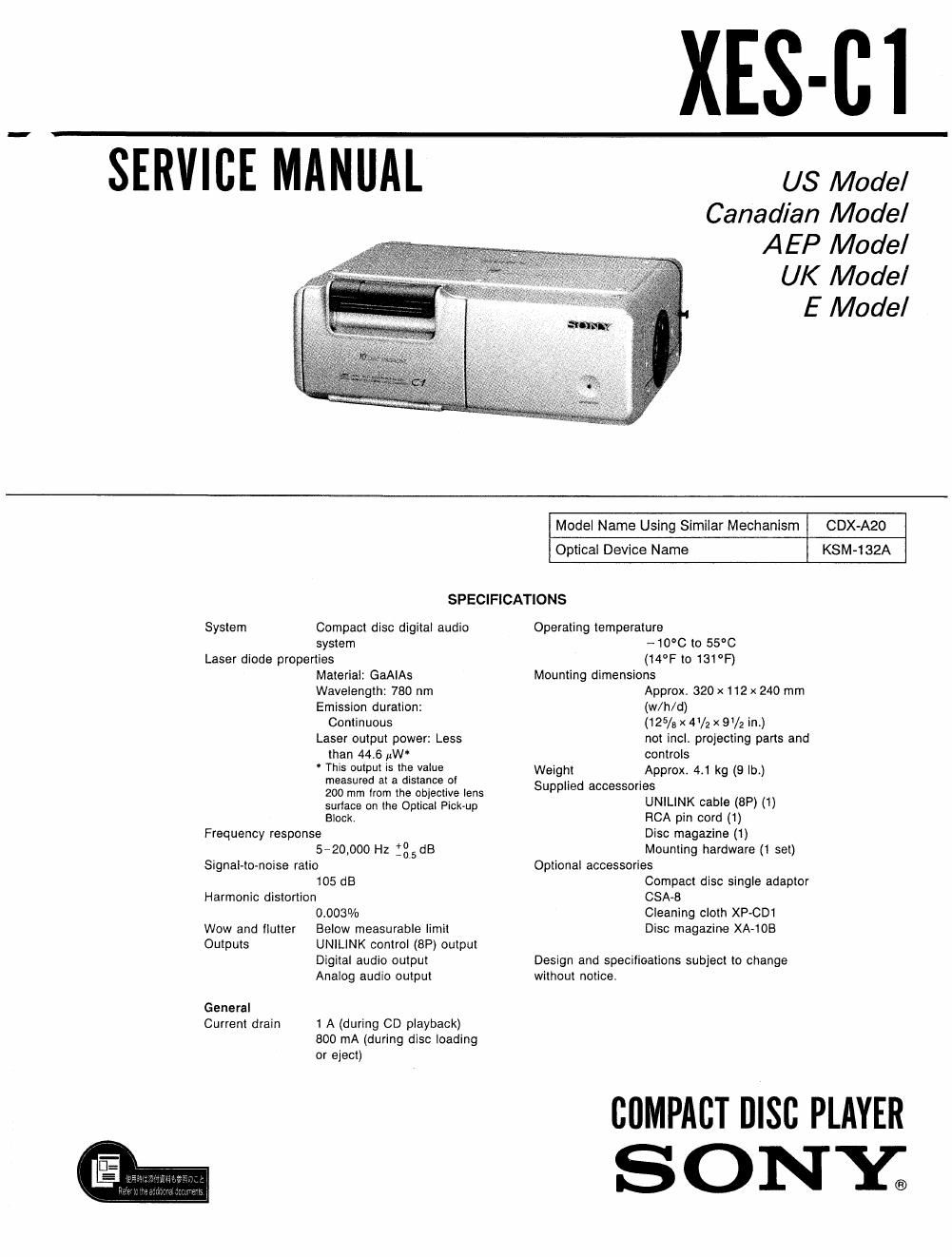
Sony xesc 1 service manual

This is the 38 pages manual for sony xesc 1 service manual.
Read or download the pdf for free. If you want to contribute, please mail your pdfs to info@audioservicemanuals.com.

Page: 1 / 38
left right
sony xesc 1 service manual

Extracted text from sony xesc 1 service manual (Ocr-read)


Page 1

XES-CI

SERVICE MANUAL

US Model
Canadian Model
AEP Model

UK Model

E Model

Model Name Using Similar Mechanism CDX-A20

KSM-132A

Optical Device Name

SPECIFICATIONS

System Compact disc digital audio
system
Laser diode properties
Material: GaAIAs
Wavelength: 780 nm
Emission duration:
Continuous
Laser output power: Less
than 4416 MW*
This output is the value
measured at a distance of
200 mm lrom the objective lens
surtace on the Optical Pick-up
Block,
Frequency response
5»2o,ooo Hz :glsdB
Signal-to-noise ratio

105 dB
Harmonic distortion

0003%
Wow and flutter Below measurable limit
Outputs UNlLINK control (8P) output

Digital audio output
Analog audio output

General
Current drain 1 A (during CD playback)
800 mA (during disc loading

or eject)

Operating temperature
-10°C to 55°C
(14°F to 131°F)
Mounting dimensions
Approx 320 x112 x 240 mm
(w/h/d)
(125/9 X 4'/2 X 9/2 in.)
not incl, projecting parts and
controls
Weight Approx 4.1 kg (9 lb)
Supplied accessories
UNlLINK cable (8P) (1)
FICA pin cord (1)
Disc magazine (1)
Mounting hardware (1 set)
Optional accessories
Compact disc single adaptor
GSA-B
Cleaning cloth XP-CD1
Disc magazine XA-1OB

Design and specifications subject to change
without notice.

summer 0130 PLAYER
SONY;

Page 2

XES-C1

Features

0 Optical digital transmission reduces noise.

. Mobil CD changer automatically changes the
discs in the disc magazine and enables you to
play the desired selections at 10 discs.

- Angle selector allows you to install the unit
vertically or horizontally, or even in a slanting
location.

- Dust~proof design for heavy-dust use.

- BSL (Brush and Slot Less) meter spins the
compact disc stably.

-Anti-vibration structure reduces the vibration
of the disc compartment,

NOTES ON HANDLING THE OPTICAL PICK-
UP BLOCK OR BASE UNIT

The laser diode in the optical pick-up block may
suffer electrostatic breakdown because of the poten-
tial difference generated by the charged electrostatic
load, etc. on clothing and the human body.

During repair, pay attention to electrostatic break-
down and also use the procedure in the printed
matter which is included in the repair parts.

The flexible board is easily damaged and should be
handled with care.

This Compact Disc player is
classified as a CLASS 1
LASER product.

The CLASS 1 LASER
PRODUCT label is located
on the rear exterior

CLASS 1 LASER PRODUCT

LUOKAN I LASERLAITE
KLASS I LASERAPPAFIAT

SAFETY-RELATED COMPONENT WARNING

COMPONENTS IDENTIFIED BY MARK A 0R DOTTED
LINE WITH MARK A ON THE SCHEMATIC DIAGRAMS
AND IN THE PARTS LIST ARE CRITICAL TO SAFE
OPERATION. REPLACE THESE COMPONENTS WITH
SONY PARTS WHOSE PART NUMBERS APPEAR AS
SHOWN IN THIS MANUAL OR IN SUPPLEMENTS PUB-
LISHED BY SONY.

TABLE OF CONTENTS

Section Title Page
Specifications .................................. 1
Features ...................................... 2
Notes on Handling The Optical Pick-up Block or

Base Unit ..................................... 2

'I. GENERAL


Installation 3

Connections 5

How to Set the Disc Magazine - . - - 5
2. DISASSEMBLY ......................... 5
3. CHANGER MECHANISM BLOCK

DESCRIPTION ------------------------- 8
4. MECHANICAL ADJUSTMENTS

Large Elevator Gear Position (Location 105)

Adjustment .............................. 14

Homing Adjustment ---------------------- 15
5. ELECTRICAL ADJUSTMENTS

1. Focus Offset Adjustment -------------- 16

2. Tracking Offset Adjustment ------------ 16

3 Tracking Gain Adjustment

(coarse adjustment) ~~~~~~~~~~~~~~~~~~~~ 17
4. Focus Gain Adjustment
(coarse adjustment) -------------------- 18

St PLL Freerun Frequency Check ---------- 18
6. DIAGRAMS
6-1. ICSOl ( #PD75116GF-E25-38E) Port Function

Description . l . . ....................... 19
6-2. Block Diagram - - ~ - ~ 21
6-3. Schematic Diagram ---------------- . 24
6-4. Servo Section Printed Wiring Boards ' - - 29
6-5. Main Section Printed Wiring Boards --------- 34
7. EXPLODED VIEWS ----------- 39
8. ELECTRICAL PARTS LIST ------------ 45

ATTENTION AU COMPOSANT AYANT RAPPORT
A LA SECURITEl

LES COMPOSANTS IDENTIFIES PAR UNE MAROUE A
sun LES DIAGRAMMES SCHEMATIOUES ET LA LISTE
DES PIECES SONT CRITIQUES POUR LA sécumré
DE FONCTIONNEMENT. NE HEMPLACER ces COM
POSANTS oua PAR DES PIECES SONY DONT LES
NUMEROS SONT DONNES DANS CE MANUEL ou
DANS LES SUPPLEMENTS PUBLIES FAR SONV.