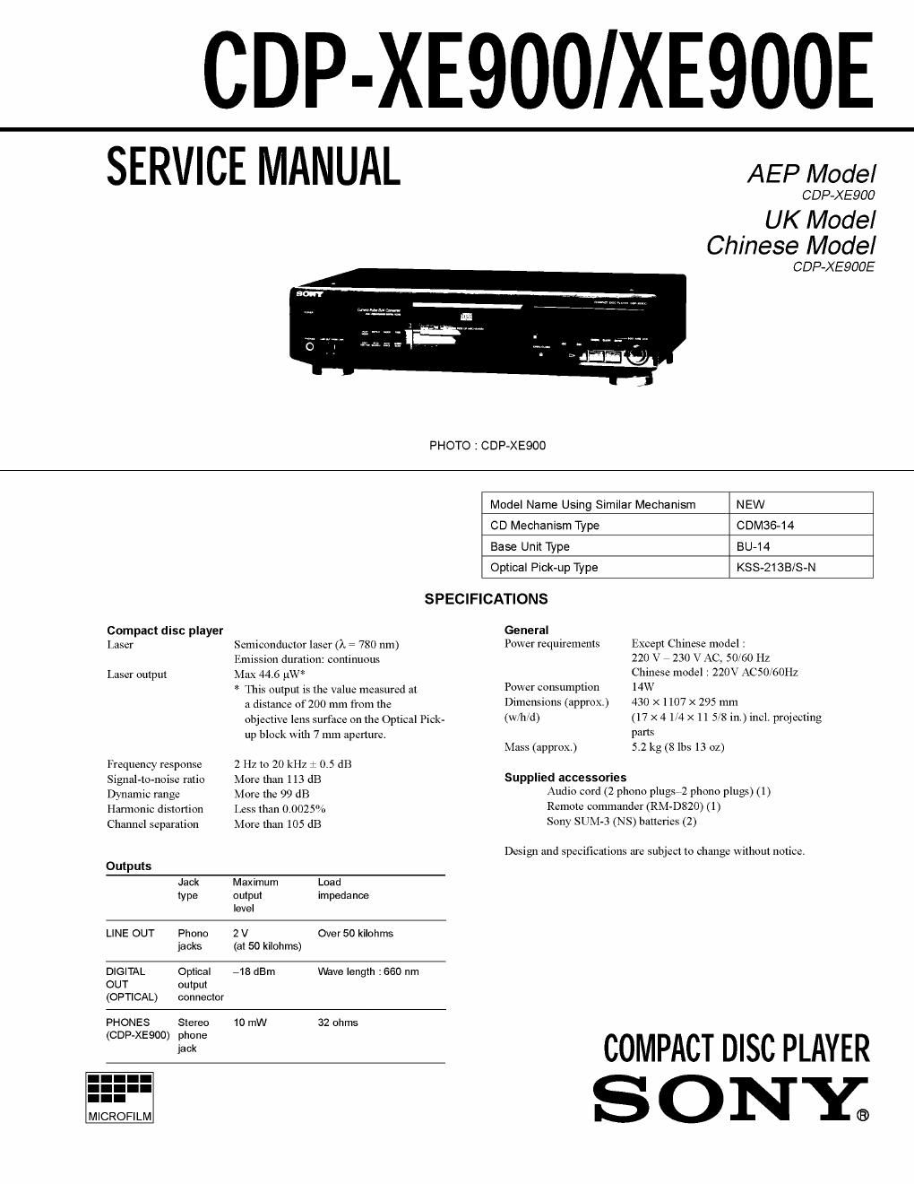
Sony xe 900 audio

This is the 29 pages manual for sony xe 900 audio.
Read or download the pdf for free. If you want to contribute, please mail your pdfs to info@audioservicemanuals.com.

Page: 1 / 29
left right
sony xe 900 audio

Extracted text from sony xe 900 audio (Ocr-read)


Page 1

CDP-XE900/XE900E

SERVICE MANUAL AEP Model

CDP-XE900

UK Model
Chinese Model

CDP-XEQOOE
PHOTO : CDP-XESOO
Model Name Using Similar Mechanism NEW
CD Mechanism Type CDM36-14
Base Unit Type BU-l4
Optical Pick-up Type KSS-21SB/S-N
SPECIFICATIONS
Compact disc player General
laser Semiconductor laser (A I 780 nm) Power requirements Except Chinese model :
Emission duration: continuous 220 V . 230 V AC. 50/60 Hz
laser output Max 44.6 ,uW" Chinese model : 220V AC50/60Hz
* This output is the value measured at POW" consumpxion 14W
'4 distance 01200 mm from the Dimensions (approx) 430 X 1107 X 295 mm
objective lens surface on the Optical Piclx- (W/Il/d) (17 X 4 1/4 X 11 5/8 i11-) incl. projecting
up block with 7 mm apenure. pans
Mime (approx) 5.2 kg (8 lbs 13 02)
Frequency response 2 Hz to 20 kHz 1 0.5 dB
Signal-to-noise ratio More than I 13 dB Supplied aecessories
Dynamic range More the 99 dB Audlo cord (2 phone plugSeZ whom plugs) (l)
Harmonic distortion Less than 0.002591; Remolfi lelmflndef (RM-320) (1)
Channel separation More than 105 dB SONY SUM-3 (NS) batteries (2)
Design and specifications are subject 10 change without notice.
Outputs
Jack Maximum Load
type uuiput impedance
level
LINE OUT Phone 2 V Over 50 kilohms
jacks (at 50 kilohms)
DIGITAL Optical 718 dBm Wave length :660 nm
OUT output

(OPTICAL) con hector

PHONES Stereo 10 mW 32 ohms

SONY

Page 2

CAU TI 0 N

Use oicontrols or adjustments or performance of procedures
other than those specified herein may result in hazardous ra-
diation exposure.

The laser component in this product
is capable of emitting radiation
exceeding the limit for Class 1.

This appliance is classified as
a CLASS 1 LASER product.
The CLASS ] LASER
PRODUCT MARKING is
located on the rear exterior.

CLASS 1 LASER PRODUCT
LUOKAN 1 LASERLAITE
KLASS I LASERAPFARAT

(XE900E)
This caution

label is located
inside the unit.

- "(VISIBLE usm maimm was». we».
Avon: Exmsu: 10 m.
flfisfiflsmmanfiflné'flfimm
DEA we IEITELSE FOR HEALING.

; mm M GIAOIALLIKIILE DHITEI'IIEBEA
mar Ari-rum mnuratvuz.

- us no "A: Dan DEL An opt-Mn
' 09.55%" An umpm

USYMLIG mums Mn nzxszi. was
mm FONENNE m 51mm.

(XEQOO)
This caution

label is located
inside the unit.

CAUTION NVISIBLE LASER wow ION WHEN OPEN AND

in iEm ocxo DEFENEO AVOID Errosunz Tl) BEAM

ADVARSEL 03w. LASERSTRALINS VED Asmwe NAP
simwznsarawom an uaE [\F FDNKYION UNDGA mam-rats:
FOR smnwo

VORSICHT UNSICHTBIARE LASERSTRAHLUNG. VIENN
Aaozcwws crown Hansirsvznntsemwe
ueEaBRUcw mcw DE L Ausssnm

VAROI AvArrAEsgx
YIINAN/AVMAYT LLE

VAR NG

Kim: OIITEWAESS
ALA mso snags

e um DEN an AR ow
mo . srwzn TRAKYA 50 Arm

ADVARSEL us

simwsnstm awvrzc

Notes on chip component replacement

- Never reuse a disconnected chip component.

- Notice that the minus side of a tanmlum capacitor may be
damaged by heat.

Flexible Circuit Board Repairing

- Keep the temperature of soldering iron around 270C during
repairing.

- Do not touch the soldering iron on the same conductor of the
circuit board (within 3 times).

- Be careful not to apply force on the conductor when soldering
or unsoldering.

SAFETY-RELATED COMPONENT WARNING !!

COMPONENTS IDENTIFIED BY MARK A: OR DOT-
TED LINE WITH MARK A ON THE SCHEMATIC
DIAGRAMS AND INTHE PARTS LIST ARE CRITICAL
TO SAFE OPERATION. REPLACE THESE COMPO-
NENTS WITH SONY PARTS WHOSE PART NUM-
BERS APPEAR AS SHOWN IN THIS MANUAL OR IN
SUPPLEMENTS PUBLISHED BY SONY.

TABLE OF CONTENTS

1. SERVICING NOTE ........................................................... 3
2. GENERAL .................................................................... 4
3. DISASSEMBLY

3-1. Front PanelAssembly ......................................................... 5
4. TEST MODE. 6

5. ELECTRICAL BLOCK CHECKING .,

6 . D IAG RA MS
6-1, Circuit Boards Location ..
6-2. Schematic Diagram - Mam Section -
6-3. Printed Wiring Board - Main Section -
6-4. Schematic Diagram - BD Section -
6-5. Printed Wiring Board - BD Section -
6-2. IC Pin Function
' ICSOl System Control,
Fluorescent Indicator Tube Drive (CXP82316-069Q) .. 26

.. 10
..11

7. EXPLODED VIEWS
7-1. Case Section
7-2. Chassis Section.
7-3. CD Mechanism Section (CDM36-l4) ..
7-4. Base Unit Section (BU- l4) ............................................... 30


8. ELECTRICAL PARTS LIST ........................................ 31

MODEL IDENTIFICATION
- BACK PANEL -

v /t
|_l

|_I

4-983-973-1EI: X13900 (AEP, German) model
4-983-973-2EI: XE900E (UK) model
4-983-973-3EI: XE900E (Chinese) model