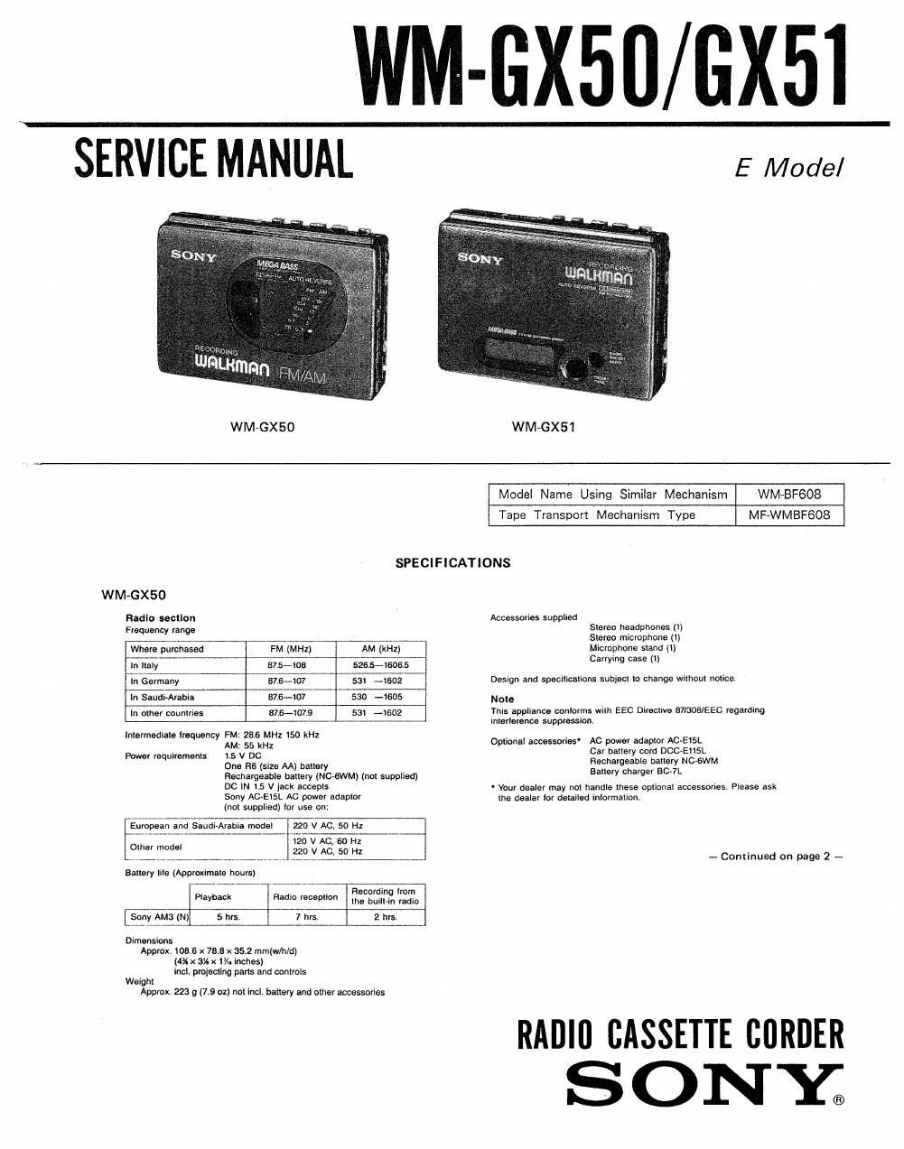
Sony wm gx 51 service manual

This is the 36 pages manual for sony wm gx 51 service manual.
Read or download the pdf for free. If you want to contribute, please mail your pdfs to info@audioservicemanuals.com.

Page: 1 / 36
left right
sony wm gx 51 service manual

Extracted text from sony wm gx 51 service manual (Ocr-read)


Page 2

WM-GX50/GX51

WM»GX51

Rndlo "mlon
Frequency range
Where purchased

FM (MI-ll) AM {III-II)

TABLE OF CONTENTS

In Italy sue-me 522-l5ll m Tme P_age
In Germany 57.5409 sat-lwz

In Saudutraoia 875-108 sat-1502 1- GENERAL

In other countries 815-108 531-1602 Paris Identification Nomenclature (WMGXBO)

Intermediate trequency Parts Identification Nomenclature (WMVGX51)

m: Egan? Service Notes ............................................................... 5

Antenna
FM: Headphones cord antenna
AM: Built-in territe bar antenna 2. DISASSEMBLY

Recording section 2-li Cabinet (Rear) Assy Removal ----------------------------- 6

Recording eynem 9, , i ..............
mack Mhannelsem _ 2. FIexthe Board Removal

Inpuk h II n 2-3. Tuner Board Removal (WM-GX50)-

icrop one nput stereo mn ac
(PLUG IN POWER) nnslllvily 0,77 mV (-60 ea) Iur lower Tuner Board Removal (WM-GX51)'
impedance microphone

Tape player nation and glnenl AD E

Frequency response (DOLBY NR on) 3 JUSTM NTS
40 Hz-15 kHz (with the PB so selector set to NORMAL or 3-1. Mechanical Measurements ----------------------

ETA . .

Onlpflom L) 3-2, Electrical Adlustments ----------------------------

Headphones (stereo mlnijack)
Load Impedance 3-3000

Power output 4. DIAGRAMS
5 w 5 t or; ' . ten . r r .

Mar'zqufiemfl: a mum 4-1~ Block Diagram (Audio Section) ------------------------- 15
1.5 v Dc - , _ .........
nechageable bane Block Diagram (Tuner Section WM 6X50) 17
One FIB (size AA) battery Block Diagram (Tuner Section WMGXSl)

DC IN 15 v jack accepts: . i . . .

. Sony AC-EISL AC power adaptor (not suppllad) 4-2. Printed Wiring Boards (Audio Section)
available In the United Kingdom tor use on 240 v ac, 4,3 Schematic Diagram (Audio Section) ................... 25
so Hz '
available in other Europaan oounlries tor use on 220 v 44. Schematic Diagram (Tuner Section WM-GXEI) 30
AC. 50 Hz , , .
available in other countries tor use an loo-tzo v no or 4-5. Printed Wiring Boards
220-240 v ac, so or so Hz ~ ................................

- Sony DCC-E115L (not supplied) lor use with l2 v car (Tuner seem WM'GX5D 33
benefit 4-6. Printed Wiring Boards

53 '3 ("W) (Tuner Section WMvGXSO) u

Battery Playback giggle" fizigzflgggi.) 4-7, Schematic Diagram (Tuner Section WM-GXEO) 37
Sony Ame (N) Approx 5 Approx, 7 Approx. 2

For maximum pertorrnance we recommend the use or alkaline 5. EXPLODED VIEWS

mm 54' Cabinet SectIon-I ............................................... 39

Dimensions _ r ,

Approx I083 X 785 X 352 mm(wlhld) 0V2. Cablnet 55(3an ........................... . ................... 40
(4: X .3"! x "In Wes) 5-3. Mechanism Sectional (MFWMBFGOS) ~
incl. protecting parts and controls
Weight 54. Mechanism Section-2 (MF-WMBFGOS) ~-
Approx. 226 9 (so up not incl. battery and other
accessories
mm 9 6 ELECTRICAL PARTS LIST ~~~~~~~~~~~~~~~~~~~~~~~~~~~~~~~~~~~~~~ 43

Lithium battery (GRZOIS) ti) Microphone (1)
Microphone stand (I) Stereo headphones ti)
Carrying case (I)

Deslgn and specifications subject I0 change without notice.

Note
This appliance ccnlorrnes with EEC Directive swans/EEC
regardlng intarlerence supplessloni

opuonnl ncceuorlcs

AC power adaptor AC-E15L
Battery charger non
Rechargeable battery Mc-st.
car battery cold DCCaEI15L
Lithium batlery cnzols

Your dealer may not handle some 0' the above listed optional
accessories. Please ask lha dealer [or delailad tnIom'Ialion.

SAFETYrR E LATED COMPONENT WARN INGIl

COMPONENTS IDENTIFIED BY MARK A OR DOTTED
LINE WITH MARK A ON THE SCHEMATIC DIAGRAMS
AND IN THE PARTS LIST ARE CRITICAL TO SAFE
OPERATION. REPLACE THESE COMPONENTS WITH
SONY PARTS WHOSE PART NUMBERS APPEAR AS
SHOWN IN THIS MANUAL OR IN SUPPLEMENTS PUB-
LISHED BY SONY.