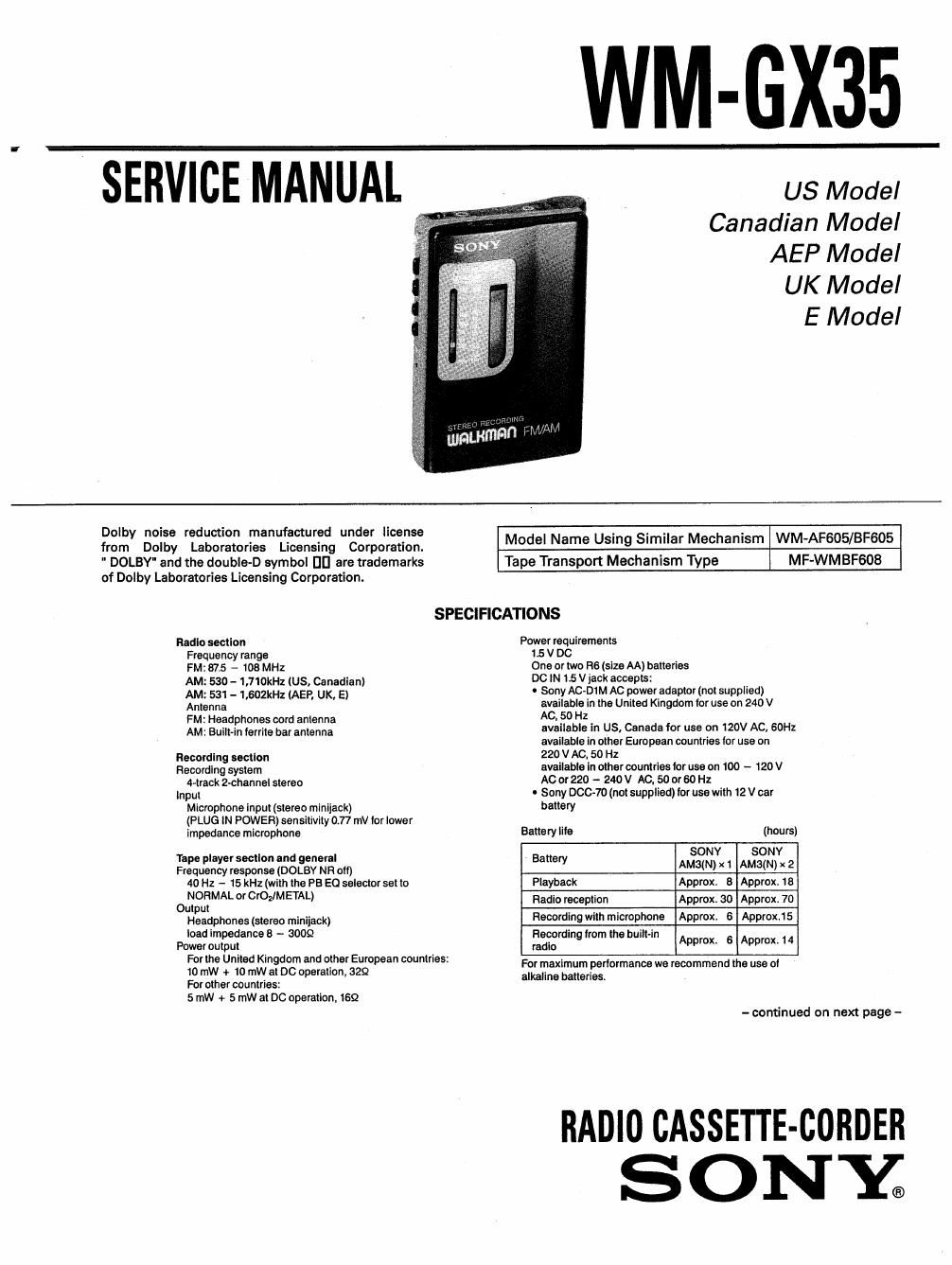
Sony wm gx 35 service manual

This is the 21 pages manual for sony wm gx 35 service manual.
Read or download the pdf for free. If you want to contribute, please mail your pdfs to info@audioservicemanuals.com.

Page: 1 / 21
left right
sony wm gx 35 service manual

Extracted text from sony wm gx 35 service manual (Ocr-read)


Page 1

_ WM-GX35

SERVICE MANUAL- . WM

Canadian Model
AEP Model

UK Model

E Model

Dolby noise reduction manufactured under license . . . .
from Dolby Laboratories Licensing Corporation. Model Name UsmgSImilar Mechanism WM-AF605/BF605

" DOLBY" and the double«D symbol DI] are trademarks Tape Transport Mechanism Type MF-WMBFGOB
of Dolby Laboratories Licensing Corporation.

SPECIFICATIONS
Radio section Power requirements
Frequency range 1.5 V DC
FM: 87.5 - 108 MHz One or two FIG (size AA) batteries
AM o - 1,710kHz (us. Canadian) 00 N 15 V lack accepts _
AM; 531 - 1.602kHz (AEP, UK, E) 0 Sony AC-DIM AC power adaptor (not supplied)
Antenna available in the United Kingdom Ior use on 240 V
FM: Headphones cord antenna AC. 50 H2

available in US. Canada for use on 120V AC, SOHz

AM: Built-in Ierrite bar antenna
available in other European countries tor use on

Recording section 220 V AC. 50 Hz

Recording system available in other countries tor use on 100 - 120 V
4vtrack 2-channel stereo AC or 220 - 240 V AC, 50 or 60 Hz

input 0 Sony DOC-70 (not supplied) tor use with 12 V car
Microphone input (stereo minijack) baflflfy
(PLUG lN POWER) sensitivity 0.77 mV lor lower _
impedance microphone Battery Ills (hours)

SONY SONY

tape player section and general Battery

Frequency response (DOLBY NR oil) AMMN) X 1 AM3(N) x 2
40 Hz - 15 kHz (with the PB E0 selector set to Playback Approx. 8 Approx. 8

0333M °' 0'0] M HAL) Radio reception Approx. 30 Approx, 70
Headphones (stereo minijack) Recording with microphone Approx. 6 Approx.15
Ioadlm dances - 3009 R dl -'

Poweroutrpeut rafir ngirom the bum in Approx. 6 Approx 14

For the United Kingdom and other European countries:
10 mW + 10 mW at DC operation, 329

For other countries:

5 rnW + 5 mW at DC operation. 16:2

For maximum perlormance we recommend the use ol
alkaline batteries

- continued on next page -

RADIO CASSETTE-CORDER
SONY;

Page 2

WM-GX35

Dimensions

Approx, 905 x1203 x 40.3 mm (w/hld)

(35/; x 43/. x 15/. inches)

incl. projecting pans and controls

Weight

Approx. 2759 (97 oz.) lncl. two batteries and other

accessories
Accessories supptied

Microphone (1) Microphone stand (1) Belt clip (1)
For the United Kingdom and other European

DOUMIIES

Stereo headphones (open-air type, i)

For other countries

Stereo earphones (open-air type. 1)

Ear adaptors are attached on the
stereo earphones, lithe
earphones do not fit your ears.
detach the ear adaptors.

Note on stereo
earphones

Put the cord behind
your neck. The knot
cannot be moved.

494%

Do not

Design and specifications subject to change without

notice.

Note

This appliance oonionns with EEC Directive
87/308/EEC regarding interierence suppression.

Optional accessories
AC power adaptor AC-Di M
Car battery cord DCC~70

Note

It a car battery cord or an N:
power adaptor not manufactured
by Sony is used, a (use must be
installed in the battery cord or
the adaptor, and the polarity of
the plug must be as illustrated.

£59;

TABLE OF CONTENTS

mien Iitla Base
2. DISASSEMBLY

2-1. Cabinet (Back) Assy Removal 4

2-2. Cabinet (Side) Removal .. 4

2~3. Cabinet (Front) Assy Removal ....................... , 5

2-4. Tuning Unit Removal ........ . .......... . ................ .. 5
3. ADJUSTMENTS 6
4. DIAGRAMS

4-1. Block Diagram ............................................ 9

4-2. Semiconductor Lead Layouts......................... 11

4-3. Printed Vifiring Board

(First Time Production) .. 11
4-4. Printed Wiring Board
(Second Time Production) ................. 16

4-5. Schematic Dimram ................... ............ 21
5. EXPLODED VIEWS

5-1. General Section .................. . ......... ............. 24

5-2. Mechanism Section-1 ................ 25

5-3. Mechanism Section2 ..................... ....... 26
6. ELECTRICAL PARTS LIST 27