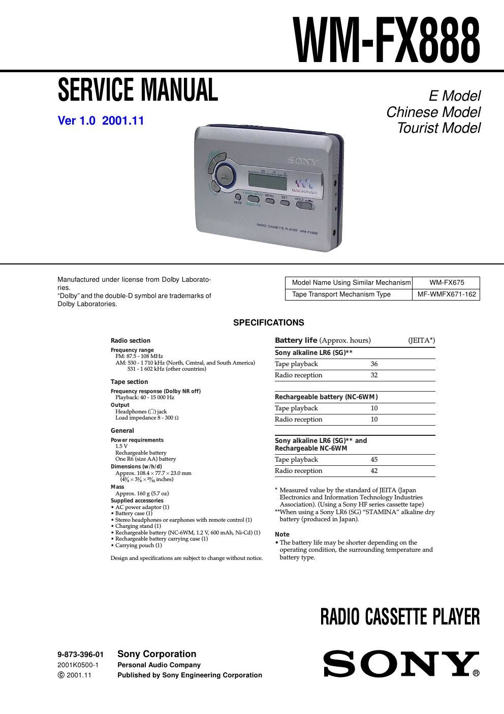
Sony wm fx 888 ver 1 0

This is the 34 pages manual for sony wm fx 888 ver 1 0.
Read or download the pdf for free. If you want to contribute, please mail your pdfs to info@audioservicemanuals.com.

Page: 1 / 34
left right
sony wm fx 888 ver 1 0

Extracted text from sony wm fx 888 ver 1 0 (Ocr-read)


Page 1

2 WM-FX888 Note on the AC power adaptor Use only the supplied AC power adaptor. Do not use any other AC power adaptor. Polarity of the plug TABLE OF CONTENTS 1. SERVICING NOTES ............................................... 3 2. GENERAL ................................................................... 5 3. DISASSEMBLY 3-1. Disassembly Flow ........................................................... 6 3-2. Case Section .................................................................... 6 3-3. MAIN Board ................................................................... 7 3-4. Belt (F2) .......................................................................... 7 3-5. Motor (Capstan/Reel) (M601) ........................................ 8 3-6. Cassette Lid Sub Assy ..................................................... 8 3-7. Reel Ornament Block Assy ............................................. 9 3-8. Holder (F) Assy (/M) ...................................................... 9 3-9. Pinch Lever (RA)/(NA) Assy ......................................... 10 3-10. Magnetic Head (Playback) (HP901) .............................. 10 4. MECHANICAL ADJUSTMENTS ....................... 11 5. ELECTRICAL ADJUSTMENTS ......................... 11 6. DIAGRAMS 6-1. Block Diagram -“ TUNER Section -“ ............................. 13 6-2. Block Diagram -“ MAIN Section -“ ................................ 14 6-3. Note for Printed Wiring Board and Schematic Diagrams ................................................ 15 6-4. Printed Wiring Board -“ MAIN Board (Side A) -“ ......... 16 6-5. Printed Wiring Board -“ MAIN Board (Side B) -“ ......... 17 6-6. Schematic Diagram -“ MAIN Board (1/2) -“ .................. 18 6-7. Schematic Diagram -“ MAIN Board (2/2) -“ .................. 19 6-8. IC Pin Function Description ........................................... 21 7. EXPLODED VIEWS 7-1. Case Section .................................................................... 23 7-2. Chassis Section ............................................................... 24 7-3. Main Section ................................................................... 25 7-4. Mechanism Deck Section-1 (MF-WMFX671-162) ....... 26 7-5. Mechanism Deck Section-2 (MF-WMFX671-162) ....... 27 7-6. Mechanism Deck Section-3 (MF-WMFX671-162) ....... 28 8. ELECTRICAL PARTS LIST ............................... 29Notes on chip component replacement - Never reuse a disconnected chip component. - Notice that the minus side of a tantalum capacitor may be dam- aged by heat. Flexible Circuit Board Repairing - Keep the temperature of the soldering iron around 270 ˚C dur- ing repairing. - Do not touch the soldering iron on the same conductor of the circuit board (within 3 times). - Be careful not to apply force on the conductor when soldering or unsoldering. SAFETY-RELATED COMPONENT WARNING!! COMPONENTS IDENTIFIED BY MARK 0 OR DOTTED LINE WITH MARK 0 ON THE SCHEMATIC DIAGRAMS AND IN THE PARTS LIST ARE CRITICAL TO SAFE OPERATION. REPLACE THESE COMPONENTS WITH SONY PARTS WHOSE PART NUMBERS APPEAR AS SHOWN IN THIS MANUAL OR IN SUPPLEMENTS PUB- LISHED BY SONY.