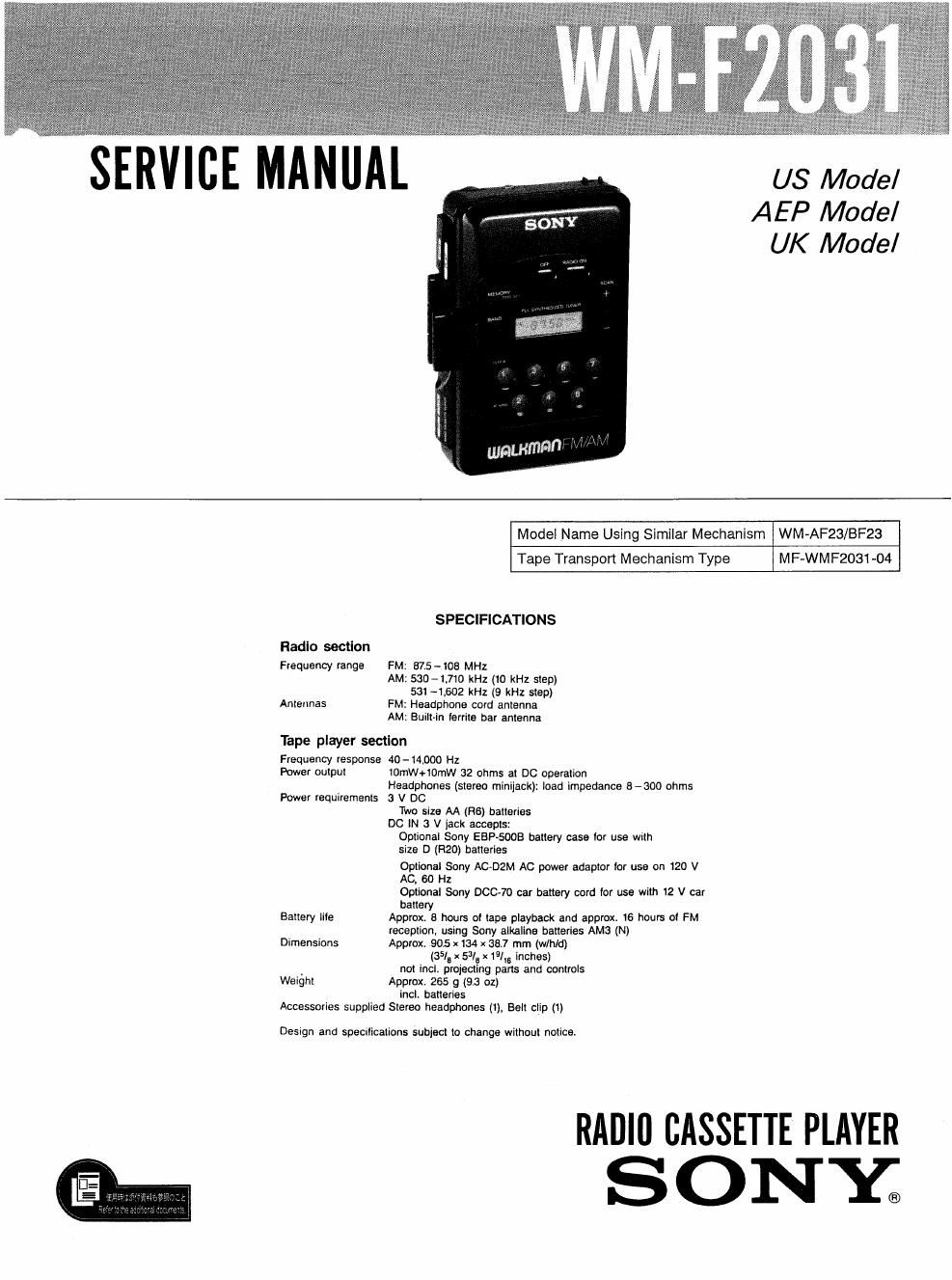
Sony wm f 2031 service manual

This is the 18 pages manual for sony wm f 2031 service manual.
Read or download the pdf for free. If you want to contribute, please mail your pdfs to info@audioservicemanuals.com.

Page: 1 / 18
left right
sony wm f 2031 service manual

Extracted text from sony wm f 2031 service manual (Ocr-read)


Page 1

SERVICE ANAu

US Model
AEP Model
UK Model

Radio section
Frequency range

Antennas

Model Name Using Similar Mechanism WM-AF23/BF23

Tape Transport Mechanism Type

M F-WM F2031 ~04

SPECIFICATIONS

FM: 575 - 108 MHZ

AM: KID-1,710 kHz (10 kHz step)
531 -1.602 kHz (9 kHz step)

FM: Headphone cord antenna

AM: Built-in ferrite bar antenna

Tape player section
Frequency response 40-14000 Hz

Power output

10mW+iOmW 32 ohms at DC operation
Headphones (stereo minijack): load impedance 6300 ohms

Power requirements 3 V DC

Battery Iile

Dimensions

Weight

Two size AA (H6) batteries
DC W 3 V jack accepts:
Optional Sony ESP-5005 battery case tor use with
size D (R20) batteries
Optional Sony AC-DZM AC power adaptor tor use on 120 V
AC. 80 Hz
Optional Sony DCC-7o car battery cord tor use with 12 V car
battery
Approx. 8 hours at tape playback and approx 16 hours oi FM
reception. using Sony alkaline batteries AMI! (Ni
Approx, 905 x134 x 38.7 mm (w/hld)
(35/, x 50/u x 1916 inches)
not incl. projecting pans and controls
Approx. 265 g (93 oz)
incl. batteries

Accessories supplied Stereo headphones (1), Belt clip (1)

Design and SpeCIIICaIIOlIS subiect to change without notice

RADlll CASSETTE PLAYER
SONY;

Page 2

WM-F203fl

Note on dlsassembly

O Disassembly is the same as that of WM-AF23/BF23
Refer to the WM-AF23/BF23 service manual.

Notes on chlp component replacement

0 Never reuse a disconnected chip component.
0 Notice that the minus side of a tantalum capacitor may
be damaged by heat.

Flexible Circuit Board Repairan

0 Keep the temperature of the soldering iron around
270 °C during repairing

Do not touch the soldering iron on the same conductor
of the circuit board (within 3 times).

Be careful not to apply force on the conductor when

soldering or unsoldenng.

WARNING !!

ADVARSEL!
Lithiumbatteri'Eksplosionsfare
Udskiftning m5 kun foretages
af en sagkyndig, 0g som
beskrevet i servicemanualen.

LITHIUM BATTERY

SHOULD ONLY BE CHANGED BY TECHNICAL
PERSONNEL THERE IS A RISK FOR EXPLOSION
AT A WRONG HANDLING.

Batteriet m5 kun udskiftes med et batteri af samme
fabrikat 0g typefi

Because of the risk for explosion the battery must
be replaced with the same type and manufacturer

SECTION 1 GENERAL

Parts Identification

Display window

O PHONES (headphones) jack
VOLUME control

MEMORY/TIME SET button

l STOP button

: new (rewind) button

¥ FF (fast-forward) button

v PLAY button

BAND select button

CLOCK button

(radio) OFF button

Tape selector, DX/LOCAL selector (US model)
Tape selector, ST/MONO selector (AEP, UK model)

RADlO ON button

Cassette holder

SCAN +I- (tunlng) buttons

km N a v jack (right side)

@O)
00

/,-

X «-Battery compartment (near)

ALARM button

Preset tuning (channel number) buttons