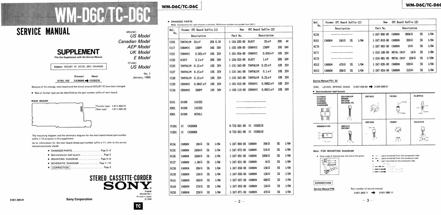
Sony wm d 6 c schematic

This is the 3 pages manual for sony wm d 6 c schematic.
Read or download the pdf for free. If you want to contribute, please mail your pdfs to info@audioservicemanuals.com.

Page: 1 / 3
left right
sony wm d 6 c schematic

Extracted text from sony wm d 6 c schematic (Ocr-read)


Page 1

WM-DbC/TC-DbC WM-D6C/TC-D6¢


O CHANGED PARTS

Note: Components for right channel is omitted. (Reference numbers are corded from 201.) Reffio Former (PC Board SUffixll) New (PC Board Suffix-12)
SERV I BE MA NUAL WM 060 Ref. Former (PC Board Suffix-11) New (PC Board Suffix-12) Description Part No. Description
' ' No.
US Model Description Part No. Description R154 --~ 1-247-890-00 CARBON 300m 5% US"
Canadian Model C103 TANTALUM 33111 20% 6.3V 1-124-220-00 ELECT 331:1 201 Av R161 CARBON 24052 5% 1/611 1-247-818-00 CARBON 30052 5% 1/6N
PPLEMENT AEP Model C117 CERAMIC lOOPF 10% 50v 1-102«108-00 CERAMIC 150111 10% 5ov R170 -- 1-247-903-00 CARBON 11152 5% 1/511
SU UK Model C121 CERAMIC 0.022;? 10% 25V 1-161-054-00 CERAMIC 0.0181111" 10% 25V 9171 - 1-216-198-00 METAL CHIP 11(9 5% 1/8"
File this Supplement with the Service Manual. E Model
C122 ELECT 2.2flF 20% 50V 1-124.255-00 ELECT 1M" 20% 50V R172 '- 1-216-081-00 METAL CHIP 22K9 5% 1/ 10d
Tc-Dsc:
Subject: DOLBY 1c «0101,2011 CHANGE US Model 0123 TANTALUM 0.15.th 10% 35V 1-131-343-00 TANTALUM 0.22m: 10% 35V R312 CARBON 4709 5% US 1-247-826-00 CARBON 62052 5% 1/611
N o 1 C127 TANTALUM 0.1511F 10% 35V 1-131-341-00 TANTALUM 0.1M 10% 35V R313 CARBON 390.9 5% US" 1-247-824-00 CARBON 51052 5% US
(Fovmer) (New) J 1955
anuary, C128 TANTALUM 0.15flF 10% 35V 1-131-343-00 TANTALUM 0.221111? 10% 351/

10101, 102 CX20068 CX20218 Service Manual P31, 32

C129 CERAMIC 0.0047IIF 10% 25V 1-161-012-00 CERAMIC 0.0082uF 10% 25V
C134 CERAMIC 560PF 10% 50V 1-102-119-00 CERAMIC 0.0015IIF 10% 50V

Because of this change, main board and the circuit around DOLBY IC have been changed.
(345) LEVER, SPRING HOOK 3-557-405-00 # 3-305-988-01

C New or former type can be identified by the part-number suffix of main board. . Semiconductor lead layouts
CX10043 25A1048-GR 2861623 151555 GLBPR1O
MAIN BOARD cxzoz18 253808
0101 DIODE 151555 - cxzoou ZSC2458

NJM3B6M 28C2453L-BL C / camoae
Former type: 1-611-494-11 NJM4558M / m
a New type: 1-611-494-12 0201 DIODE 181555 - ". ® W
a 111, c
V mode

D301 DIODE HZ3AL1. ma:

E anode

1/11
2801020 152837 NJL5141 E
mm 10 cxzooes 8-752-021-80 10 moms MMMMRS 25mm
2502001 W m a?
10201 IC CX20068 3-752-021-30 1C CX20218 ,, g \1/2 t
The mounting diagram and the schematic diagram for the main board whose part-number 31 5:] 1 H
suffix is 12 are given in this suppliment. $313 B W 11:}_ 3
As to information for the main board whose part mm. mm issued. R134 CARBON 18KS2 5% 1/ON 1-247-869-00 CARBON 391112 5% mm
0 CHANGED PARTS .................. Page 2-3 R135 CARBON 2401112 571 I/GW 1-247-872-00 CARBON 511152 5% 1/611 Note: FOR moumme DIAGRAM
O Semiconductor lead layouts .............. Page 3
. MOUNTING DIAGRAM .............. Page 4-6 R136 CARBON 240119 5% 1/6 1247-89100 CARBON 3301(9 5% 1/6 9 Color code of sleeving over the end of the jacketr : 0.: 2:: :::r::::: 2:: :2: :anginzntsflie
0 SCHEMATIC DIAGRAM ............ Page 7-10 R137 CARBON 1.8151 5% US 1-247-831-00 CARBON 1K9 5% US 0 l 2 part mounted on the conductor side.
--------------- Page 3 R138 CARBON 20st 5% 1/611 1-247-858-00 CARBON 131112 571 um : :1; y
STERE 0 CASSETTE CBRDER R139 CARBON 15m 5% 1/611 1-247-858-00 CARBON 13m 5% 1/6li "" """
R141 CARBON 5609 5% I/CW 1-247-827-00 CARBON 6809 5% 1/6N
® R149 CARBON 27K§2 5% US" 1-247-859»00 CARBON 151152 5% US
English Service Manual P38 Part number of service manual
3511061354 R150 CARBON 22119 5% US 1-247-371-00 CARBON 471152 5% 1/611 - 995134341 _. 9.951.335
Printed in Ja n
9-951-385-81 Sony Corporation ©1325

#2_ _34_