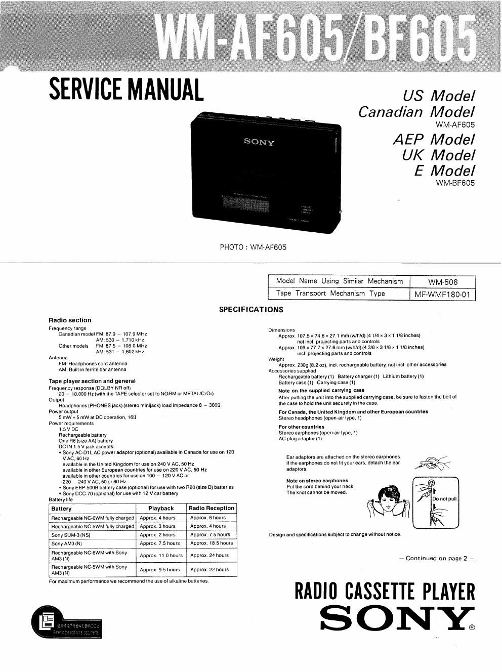
Sony wm af 605 service manual

This is the 30 pages manual for sony wm af 605 service manual.
Read or download the pdf for free. If you want to contribute, please mail your pdfs to info@audioservicemanuals.com.

Page: 1 / 30
left right
sony wm af 605 service manual

Extracted text from sony wm af 605 service manual (Ocr-read)


Page 1

ERVlc MANUAL

US Model
Canadian Model

WM~AF605

AEP Model
UK Model
E Model

WM-BF605
PHOTO : WM-AF605
Model Name Using Similar Mechanism WM-506
Tape Transport Mechanism Type MF-WMF180-01
SPECIFICATIONS
Radio secIlon
Frequency range Dlmenslons

Canadlan model FM: 973 - I07 9 MHZ
AM: 530 A 1,7I0kHI

Olhei models FM. 87 5 -- I08 0 MHZ
AM' 51 - 1.6021011

Anlenna
FM' Headphones cold anlenna
AM: BullHn Ierlile bar anIenna

Tape player sectlon and genevaI
Frequency response [DOLBY NR all)

20 - IB,000 Hz (WlIh lhe TAPE seleclol sel Io NORM of METAL/C102)

Outpul

Headphones (PHONES jack) (slereo minljack) load Impedance 8 - 3009

Power Dulpul

5 mW + 5 mW 31 DC aperallon. loll
Power requlremems

l 5 v DC

Rechargeable ballory

One as (SIZE AA) oarlery

Dc IN 15 v jack accepls:

- Sony AC~DI L Ac power adaplor |opllonal) avallable in Canada lor use on I20

VAC.60HZ

avallable In Ihe Unllsd Kingdom Io! use on 240 V AC 50 Hz
avallable in OMB! European counlries In! use on 220 V AC. 50 HI
avallable In omel countries lo! use on I00 - 120 V AC 0'

220 7 240 V AC, 50 m 60 H1

' Sony EBP~SODB Daflery Case (opllonall lo! use wilh lwo H20 {size D) ballelies
- Sony DCC-7o (optional) lor use mm 12 v oar berrery

Ballely llle

Bauery

Playback

Radlu Reception

Rechargeable NC-GWM lully charged

Approx. 4 hours

Approx. 6 hours

Rechargeable NC-SWM lully charged

Approx. 3 hours

Applox. 4 hours

Sony sumeamsl

Approx 2 hours

Approx 7.5 hours

Sony AMa (N)

Approx 7 5 hours

Approx la 5 hours

Rechargeable NCAGWM wrrh Sony
AM3 IN)

Approx 11 chours

Approx. 24 hours

Rechargeable Nc-st wrrh Sony
AMCI 1N)

Approx 9 5 hours

Approx. 22 hours

For maxlmum parlarmance We recommend Ihe use 01 alkallne bailelies

Approx 107.5 x 74 6 x 27 I mm [win/6H4 1/4 x 3 x1 I/B lnches)
nol rncl plolecling pans and conlrols
Approx loox 77.7 x 27 6 mm (win/d) (A 3/9 x 31/8 x I no rnches)
lncl prolecllng pans and oonlrols
Welghl
Approx 2309012 01). lncl. rechargeable ballely. nol lrch olherecoessories
Accessones supplled
Rechargeable oahory (I) Bellery charger (I l Lilhlum ballery (ll
Ballery case (1) Carrying case 11)
Note on III: supplIed calryIng can
Allel pulllng lhe unll lnlo [he suppllea callylng case, be sure to raslell me be m
lhe case In hold me unII seculely in ma case.

For Canada. lhe Unlled Klngdom nnd olher Europe-n coumrlu
Slereo headphones (openralr lype, 1)

F0! other counIrles
Stereo earphones (open-ail type. 1)
AC plug adaplor (ll

Ear adaplols ale arrached on lhe slereo earphones
ll lhe earphones do nol m your ears, delaoh lhe ear )%
adaplors,

Nola on alereo earphones
Pu! lhe cord behind your neck,
The knol cannol be moved I

Do nol pull.

l

Desrgn and speclllcallons sublecl lo change wrlhoul nolroe

- Cominued on page 2 -

RADIfl CASSETTE PLAYER

SONx

Page 2

Not
This applianco conforms wlm sec dlroctlves 76/889 and 92/499 regarding ,TABLE OF CONTENTS
mlertoronce suppression.

Opllonal accnwrlu . .
Ballary case EBHaoa AC power adaptor AC-DIL Sic-91 M P_ag_e_
Car ballary cord Doc-70 Lithium battery cn-zms

V001 duller may not handle some o! "10 above listed oplional accessories. Please
ask the dealer tor detailed inlwnalion about the oplional accessories uvmlabla in
your counlly.

Specmcationl
Note

Ila car ballery cord or an AC power adaptor not manulacluved ?

by Sony is used. : luse musl be installed in Ina battery com or

meadaptor.andimmamynnneplugmusrbeasmusuarea 2. DISASSEMBLY5
3 ADJUSTMENTS 6

4. DIAGRAMS
4-1. Printed Wiring Board -Audio Section-nn-w-"Q
4-2. Schematic Diagram -Audio Section- 11
4%. Schematic Diagram -Radio Section- 14

4-4. Printed Wiring Board ~Radio Section- 17
4-5.1C Block Diagram ~- 20
4-6. Semiconductors Lead Layout--- 22

5. EXPLODED VIEWS

5-1. Cabinet....a...nu....u...................4................. 23
24
~25

5-2. Mechanism_1...........
53 Mechanism-2-~

6. ELECTRICAL PARTS LIST ...... 25

Flexible Circuit Board Repairing

0 Keep the temperature of the soldering iron around
270°C during repairing.

0 Do not touch the soldering iron on the same conduc-
tor of the circuit board (within 3 times).

0 Be careful not to apply force on the conductor when
soldering or unsoldering.

Notes on chip component replacement

0 Never reuse a disconnected chip component.
0 Notice that the minus side of a tantalum capacitor
may be damaged by heat.