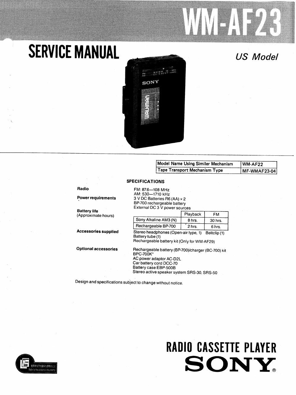
Sony wm af 23 service manual

This is the 12 pages manual for sony wm af 23 service manual.
Read or download the pdf for free. If you want to contribute, please mail your pdfs to info@audioservicemanuals.com.

Page: 1 / 12
left right
sony wm af 23 service manual

Extracted text from sony wm af 23 service manual (Ocr-read)


Page 1

SERVICE MANUAL

US Model

Radio

Power requirements

Battery lite
(Approximate hours)

Accessories supplied

Optional accessories

Model Name Using Similer Mechanism

WM-AF22

Tape Transport Mechanism Type

MF-WMAF23-O4

SPECIFICATIONS

FM: B7.6~108 MHZ

AM: 530-1710 kHz

3 V DC Batteries H6 (AA) x 2
BP-7OD rechargeable battery
External DC 3 V power sources

Playback FM
Sony Alkaline AM3 (N) 8 hrs, 30 hrs.
Rechargeable BP-7OO 2 hrs. 6 hrs,

Stereo headphones (Open-air type, 1) Beitclip (1)
Battery tube (1)
Rechargeable battery kit (Only ior WM-AF29)

Rechargeable battery (BP-700)/charger (BC-700) kit
BPCv700K

AC power adaptor AC-DZL

Car battery cord DOC-70

Battery case EBP

Stereo active speaker system SRS-SO. SIRS-50

Design and specifications subject to change without notice.

RAIIIII CASSETTE PLAYER

SONY;

Page 2

WM-AF23

Flexible Circuit Board Repairing

Keep the temperature of the soldering iron around

270°C during repairing.

Do not touch the soldering iron on the same conduc-

tor of the circuit board (within 3 times).

0 Be careful not to apply force on the conductor when

soldering or unsoldering.

Notes on chip component replacement

0 Never reuse a disconnected chip component.

0 Notice that the minus side of a tantalum capacitor

may be damaged by heat.

SECTION 1
DISASSEMBLY

Louti n and shape of claws

The symbols (0 -$) show the order to uncouple the
linkage of the claw, and names of the parts.


Rear Cabinet Assy

Front Cabinet Assy

Cassette Holder Any

N to: Follow the disassembly procedure the numerical order given.

To I: Precision Screwdrivers ( G) , width 03mm, 1.4mm, and 2.0mm)
Adhesive tape l-Zcm
Wedge (hand made)

Material . . . soft plastic (such as PVC) etc.
Sizes are for the reference.

6mm 2mm

3mm

10mm

0.3mm

Ill Cassette Holder Removal

00pm the cassette holder.

0 While pressing the edge of the cassette holder, pull up it
in order to take off the cassette holder.

OTake off the end of coil Spring with a precision screw-
driver (width: 0.8mm).

[2] Rear Cabinet Removal

0 Insert a precision screwdriver (width: 2,0mm) into the
slit of front cabinet, lift the front cabinet as shown in
the figure for making a clearance ( 9 ).

Insert a wedge in the clearance.