Sony wm 507 service manual

This is the 15 pages manual for sony wm 507 service manual.
Read or download the pdf for free. If you want to contribute, please mail your pdfs to info@audioservicemanuals.com.

Page: 1 / 15
left right
sony wm 507 service manual

Extracted text from sony wm 507 service manual (Ocr-read)


Page 1

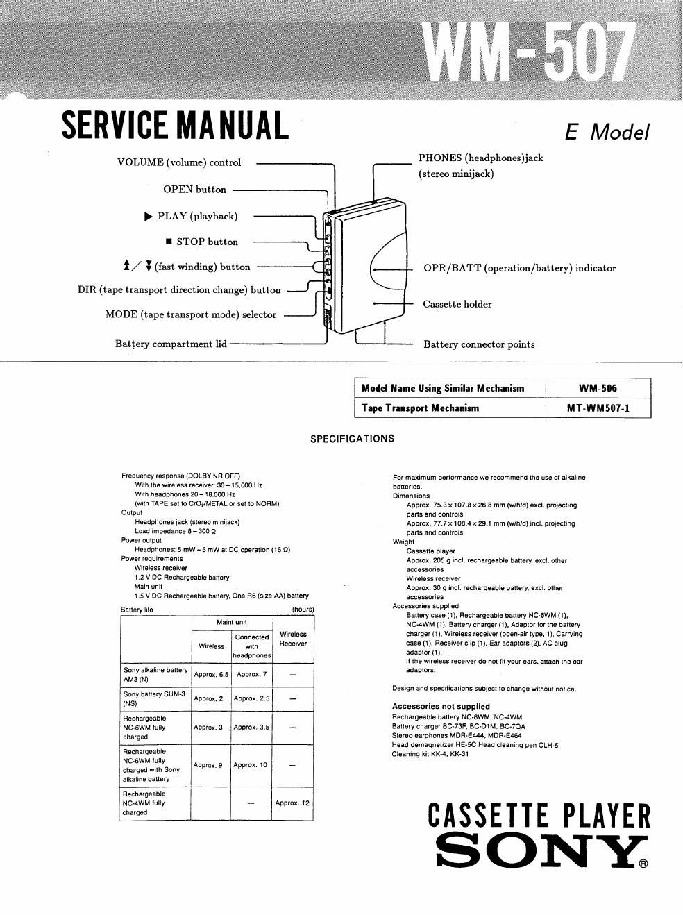
SERVICE MANUAL

VOLUME (volume) control
OPEN button

} PLAY (playback)

I STOP button

/ ¥ (fast winding) button
DIR (tape transport direction change) button

MODE (tape transport mode) selector

Battery compartment lid


E Model

PHONES (headphones)ij
(stereo minijack)

OPR/BATT (operation / battery) indicator

Cassette holder

Battery connector points

Model Name Using 5 r Mechanism WM-SM
Tape Transport Mechanism MT-WMSW-l
SPECIFICATIONS

Frequency resoonse (UOLBY NR OFF)

With the wireless recewer: 30 - I5.DOO Hz

With headphones 20-18000 HZ

(wllh TAPE set to CrOflMFIAL or set to NORM)
Output

Headphones jack (stereo mimjack)

Load impedance 5- 300 52
Power pulnut

Headphones: 5 mW +5 I'nW ill DC operatlon (IS 9)
Power leqwremenls

Wireless receiver

1.2 v DC Rechargeable battery

Main unit

1.5 V DC Rechargeable battery. One H6 (size AA} battery

Battery Ills (hours)
Malnt unvl
Connected WINE
WI'eless WIIII Hecetver
headphones

Sony alkaline barlery

AM 3 (N) Approx. 6.5 Approx. 7 -

Sony ballery SUMJ

A . . -
(NS) DDlox,2 Approx 25

Rechargeable
NC-GWM lully Approx. 3 Approx. 3.5 -
charged

Rechargeable
NC-BWM IuIly
charged wllh Sony
alkalme battery

Approx. 9 Approx. l0 -

Rechargeable
NCJWM Iully -- Approx. 12

charged

Fol maximum podormance we recommend the use DI alkaline

batteries.

Dimensions
Approx. 753 x 107.3 x 26.8 mm (w/h/a) excl. projecting
pans and conlrols
Approx. 77.7 x 103.4 x 29.1 mm (w/hld) incl. projecting
parts and controls

Welght
Cassette player
Approx. 205 9 Incl. rechargeable ballery, excl. olher
accessories
Wireless receiver
Approx. 30 9 met. rechargeable battery, excl. other
accessories

Accessories supplied
Battery case (1). Rechargeable battery NC,-6WM (1).
NC~4WM (1). Bartery charger (1). Adaptor lor the battery
charger (1). Wireless receiver (open-air type. 1). Carrying
case (1). Recelver clip (1 ), Ear adaptors (2), Ac plug
adaplor (1).
II the WIraless recervel- do not 111 your ears. altach the ear
adaplors.

Destgn and specrlrcalions subject to change WIlhout natlce.

Accessories not supplied

Rechargeable battery NC-GWM. NC-4WM

Battery charger BC-73F. BCADI M, 3070A

Stereo earphones MDRAEW. Mnnrsrae

Head demagnetlzer HE-SC Head cleanlng pen CLHS
Cleaning kit KKA. KK-31

CASSETTE PLAYER
SONXQ

Page 2

WM-507 I

TABLE OF CONTENTS

Section

Specification


Servicing Note .
1. GENERAL
2. ADJUSTMENTS
3. DIAGRAMS
3-1. Semiconductor Lead Layouts
3-2. 10 Block Diagram
3-3. Printed Wiring Board

i1?
. . . . p,
as to N t-I to

3-4. Schematic Diagram - Audio section - ............. 11

3-5. Schematic Diagram - Transmitter section - 14
4. EXPLODED VIEWS

4-1. Cabinet


4»2. Mechanism-1 .
4-3. Mechanism-2 ................................................. 19
5. ELECTRICAL PARTS LIST .............................. 20

Dolby noise reduction manufactured under license from
Dolby Laboratories Licensing Corporation.
DOLBY and the double-D symbol [1] are trademarks

of Dolby Laboratories Licensing Corporation.

SERVICING NOTES
Flexible Circuit Board Repairing

-Keep the temperature of the soldering iron around 270
'C during repairing.

-Do not touch the soldering iron on the same con-
ductor of the circuit board (within 3 times).

-Be careful not to apply force on the conductor when

soldering or unsoldering.

N tes on Chip Component Replacement

-Never reuse a disconnected chip component.

-Notice that the minus side of a tantalum capacitor
may be damaged by heat.

Precautions on Service

When performing service or function checks when the
audio board has been removed, depress the PLAY (b)
button to turn ON the S901 (POWER) and $902
(PLAY).

AUDIO BOARD - Component side -

4:] IC301

IC601. 5502 D
I] ® (PLAY)

1.3 V
supplied

$901 (POWER)

Alligator clip

How to remove the transmitter board since the
transmitter board is attached to the cassette lid with a
double-sided adhesive tape, peel it off in numerical
order by inserting a pair of tweezers or similar tools,
taking care not to bend it strongly.

Cassette lid 9 Pair of tweezers

6 Note :

-Use a pair of tweezers with thin tips.
-Make sure not to lift the pair of
tweezers upward.