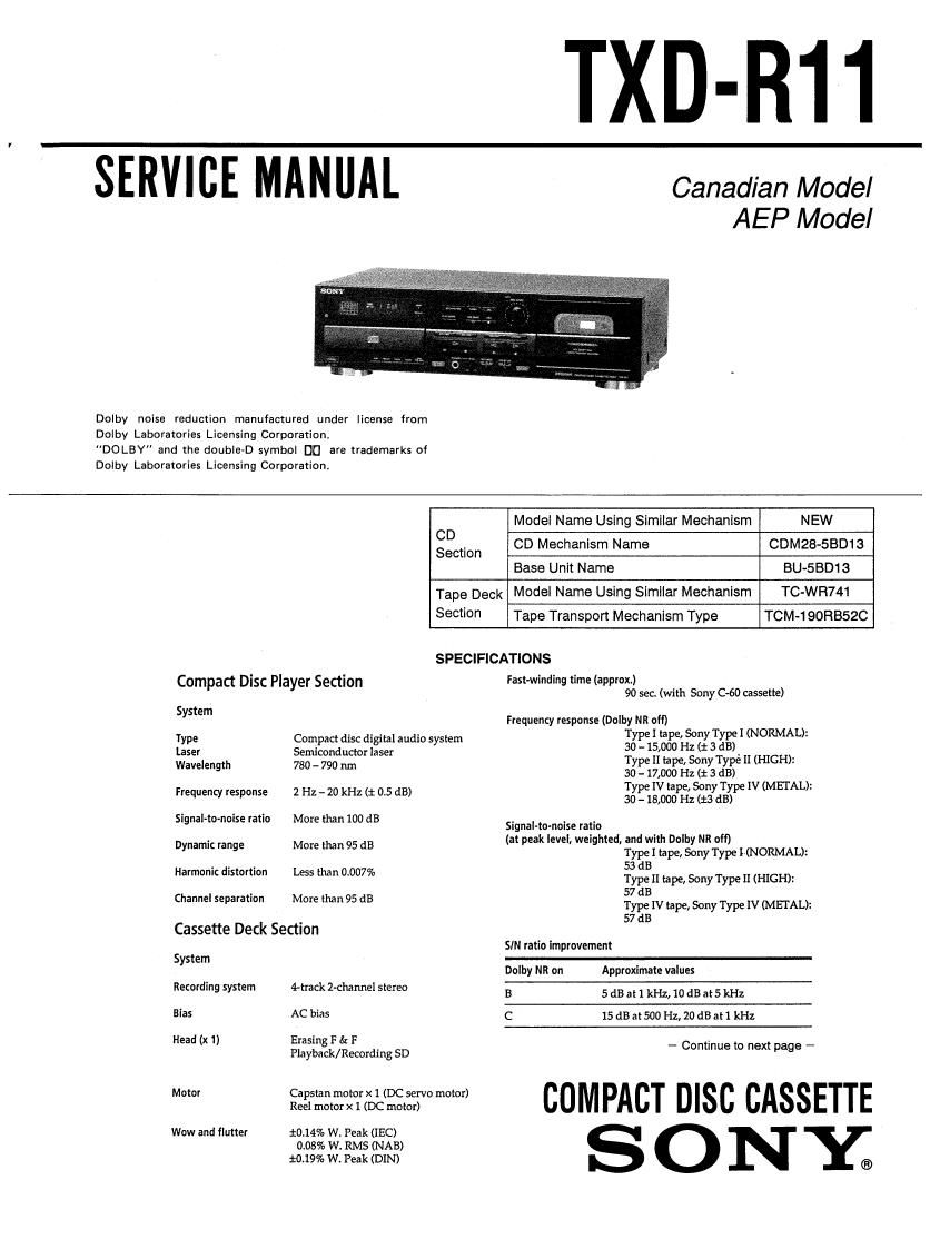
Sony TXDR11 cd sm

This is the 32 pages manual for Sony TXDR11 cd sm.
Read or download the pdf for free. If you want to contribute, please mail your pdfs to info@audioservicemanuals.com.

Page: 1 / 32
left right
Sony TXDR11 cd sm

Extracted text from Sony TXDR11 cd sm (Ocr-read)


Page 1

TXD-R11

SERVICE MANUAL

Dolby noise reduction manufactured under license from
Dolby Laboratories Licensing Corporation,
"DOLBY" and the double-D symbol D0 are trademarks of
Dolby Laboratories Licensing Corporation.

Canadian Model
AEP Model

Model Name Using Similar Mechanism NEW
CD . CD Mechanism Name CDM28-SBD13
Section

Base Unit Name BU-SBD13
Tape Deck Model Name Using Similar Mechanism TC-WFI741
Section Tape Transport Mechanism Type TCM-190RBSZC
SPECIFICATIONS

Compact Disc Player Section

System

Type

Laser

Wavelength
Frequency response
Signal-to-noise ratio
Dynamic range

Harmonic distortion

Channel separation

Compact disc digital audio system
Semiconductor laser

780 - 790 nm

2 Hz- 20 kHz (:t: 0.5 dB)

More than 100 dB

More than 95 dB

Less than 0.007%

More than 95 dB

Cassette Deck Section

System
Recording system
Bias

Head (x 1)

Motor

Wow and flutter

4-track Z-channel stereo

AC bias

Erasing F 6: F

Playback/ Recording SD

Ca pstan motor x 1 (DC servo motor)
Reel motor x 1 (DC motor)

10.14% W. Peak (IEC)

0.08% W. RMS (NAB)
10.19% We Peak (DIN)

Fast-winding time (approx)
90 sec. (with Sony G60 cassette)

Frequency response (Dolby NR off)
Type I tape, Sony Type I (NORMAL):
30 - 15,000 Hz (i 3 dB)
Type II tape, Sony Type [I (HIGH):
Ito-17,000 Hz (1 3 dB)
Type IV tape, Sony Type lV (METAL):
30- 18,000 Hz (1:3 dB)

Signal-to-nolse ratio

(at peak level, weighted. and with Dolby NR off)
Type I tape, Sony Type HNORMAL):
53 dB

Type II tape, Sony Type ll (HIGH):

57 dB

Type IV tape, Sony Type IV (METAL):
57 dB

SIN ratio improvement

Dolby NR on Approximate values
B 5dBatIkHz,10dBat5kHz
C 15dBat500Hz,20dBat1kHz

- Continue to next page -

COMPACT DISC CASSETTE
S O N I

Page 2

Harmonic distortion Type] tape, Sony Type I (NORMAL):
0.4% (160 nWb/m 315 Hz, 3rd HD.)
Type IV tape, Sony Type IV (METAL):

148% (ED nWb/m 315 Hz, 3rd HDI)

Inputs
Iatk type Maximum input sensitivity
TAPE IN Phono jacks 0.16 V (input impedance:
47 kiloth)
Outputs
lack type Maximum output load
level impedance
TAPE OUT Phono jade 0.5 V Over
(FIXED) (at a load 10 kilohms
impedance of
47 kilohms)
CD OUT Phono jacks 2 V Over
(FIXED) (at a load 10 kilohms
impedance of
50 kilohms)
PHONES Stereo phone 0 - 3 mW
(VARIABLE) jack (at a load
impedance of
32 ohms)

General

Power requirements

Where purchased Power requiremens
Europe HOV-230 VAC, 50/60 Hz
Canada 120 VAC, 60 Hz

Power consumption 23 W

Dimensions 430 x 125 x 280 mm (w/h/d)
( 17X 47/5 x11 1/3 inches)
Mass (approx.) 45 kg (91b,15 oz.)

Supplied accessories Audio connecting cord (2 phone

plugs - 2 phone plugs) (3)

Design and specifialtions are subject to change without notice.

SAFETY-RELATED COMPONENT WARNING

COMPONENTS IDENTIFIED BY MARK A 0R DO'ITED
LINE WITH MARK A ON THE SCHEMATIC DIAGRAMS
AND IN THE PARTS LIST ARE CRITICAL TO SAFE
OPERATION. REPLACE THESE COMPONENTS WITH
SONY PARTS WHOSE PART NUMBERS APPEAR AS
SHOWN IN THIS MANUAL OR IN SUPPLEMENTS PUB-
LISHED BY SONY.

ATrENTlON AU COMPOSANT AYANT RAPPORT
A LA sEcunrrEr

LES COMPOSANTS IDENTIFIES PAH UNE MARQUE A
sun LES DIAGRAMMES SCHEMATIQUES ET LA LISTE
DES PIECES SONT CRITIQUES POUR LA sEcumTE
DE FONCTIONNEMENT. NE REMPLACEFI cEs COM-
POSANTS QUE PAR DES PIECES SONY DONT LES
NUMEROS SONT DONNES DANS cE MANUEL ou
DANS LES SUPPLEMENTS PUBuEs PAR SONY.

TABLE OF CONTENTS


Section Title Page
Specifications -------------- 1
Servicing Notes ------------ 3
1. GENERAL

Location of Controls 4
2. DISASSEMBLY ......................... 5
3. ADJUSTMENTS
3-1. Mechanical Adjustments ~~~~~ 6
3-2 Electrical Adjustments ------ 6
4. DIAGRAMS
4~l. Primed Wiring Boards

- Panel and Mechanism Section - ---------- 12
4-2. Schematic Diagram

- Panel and Mechanism Section - ---------- 15
4-3. Schematic Diagram - Main Section - ~ - ' - - - - 20
4-4. Printed Wiring Boards - Main Section - . 25
4-5 IC Pin Function Description ---------------- 29
5. EXPLODED VIEWS -------------------- 33
6. ELECTRICAL PARTS LIST ------------ 38

CLASS 1 LASER PRODUCT
LUOKAN 1 LASERLAITE

KLASS I LASERAFPARAT

This appliance is classified as a CLASS 1 LASER product
The CLASS 1 LASER PRODUCT MARKING is located on the
rear exterior.

The following caution label is located inside of the unit.

WHOM :
Mensa. '
who! :
vAaNINo

CAUTION

Use of controls or adjustments or performance
of procedures other than those specified herein
may result in hazardous radlatlon exposure.