Sony tr 620 service manual

This is the 2 pages manual for sony tr 620 service manual.
Read or download the pdf for free. If you want to contribute, please mail your pdfs to info@audioservicemanuals.com.

Page: 1 / 2
left right
sony tr 620 service manual

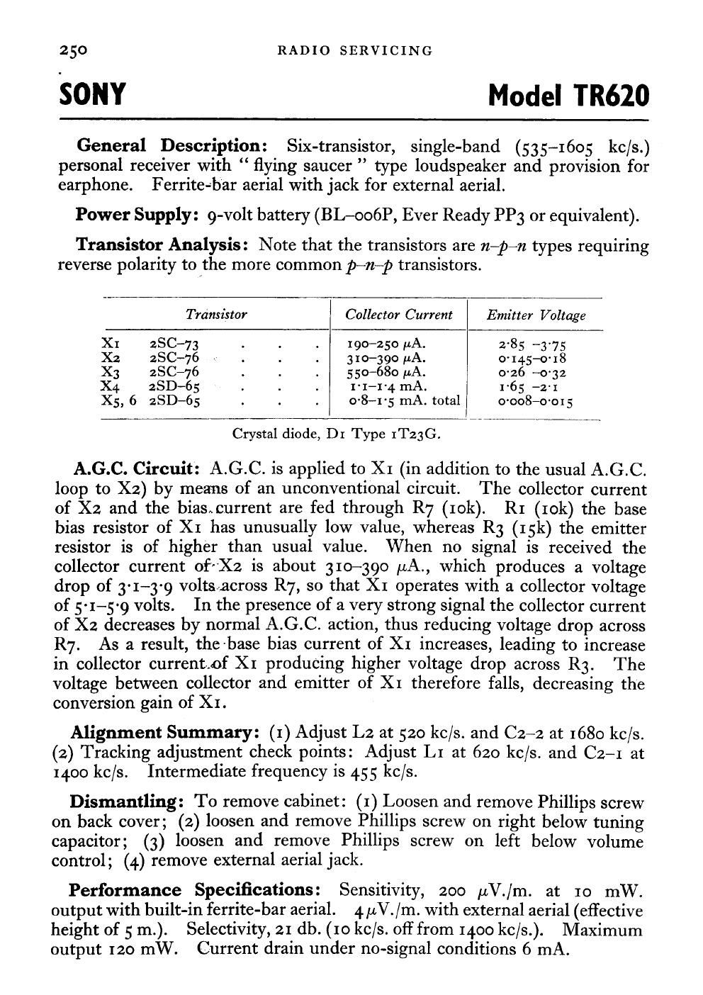
Extracted text from sony tr 620 service manual (Ocr-read)


Page 1

250 RADIO SERVICING

SONY Model TR620

General Description: Six-transistor, single-band (53 5-1605 kc/s.)
personal receiver with flying saucer type loudspeaker and provision for
earphone. F erriteab'ar aerial with jack for external aerial.

Power Supply: 9-volt battery (BL-oooP, Ever Ready PP3 or equivalent).

Transistor Analysis: Note that the transistors are n-p-n types requiring
reverse polarity to the more common p~n-p transistors.

Transistor l Collector Current Emitter Voltage
XI 28C-73 . . . 190-250 pA. 285 ~3'75
X2 28C-76 . . . 3 10-390 uA. o' 14.5-0' 18
X3 28C-76 . . . 5 50-680 FA. o~26 ~o~ 32
X4 28D-65 . . . 1-1-14 mA. 1-65 -2-r
X5, 6 st-65 . . . 0'8-1-5 mA. total 0'008-0-015

Crystal diode, D1 Type IT23G.

A.G.C. Circuit: A.G.C. is applied to X1 (in addition to the usual A.G.C.
loop to X2) by means of an unconventional circuit. The collector current
of X2 and the biasncurrent are fed through R7 (10k). R1 (10k) the base
bias resistor of XI has unusually low value, whereas R3 (15k) the emitter
resistor is of higher than usual value. When no signal is received the
collector current ofrXz is about 310-390 uA., which produces a voltage
drop of 3-1-3-9 voltsacross R7, so that XI operates with a collector voltage
of 51-5-9 volts. In the presence of a very strong signal the collector current
of X2 decreases by normal A.G.C. action, thus reducing voltage drop across
R7. As a result, the-base bias current of XI increases, leading to increase
in collector current..of XI producing higher voltage drop across R3. The
voltage between collector and emitter of XI therefore falls, decreasing the

conversion gain of XI.

Alignment Summary: (1) Adjust L2 at 520 kc/s. and C2-2 at 1680 kc/s.
(2) Tracking adjustment check points: Adjust L1 at 620 kc/s. and CZ-I at
1400 kc/s. Intermediate frequency is 45 5 kc/s.

Dismantling: To remove cabinet: (I) Loosen and remove Phillips screw
on back cover; (2) loosen and remove Phillips screw on right below tuning
capacitor; (3) loosen and remove Phillips screw on left below volume
control; (4.) remove external aerial jack.

Performance Specifications: Sensitivity, 200 ,uV./m. at 10 mW.
output with built-in ferrite-bar aerial. 4 ,uV. /m. with external aerial (effective
height of 5 m.). Selectivity, 21 db. (Io kc/s. OH from 1400 kc/s.). Maximum
output 120 mW. Current drain under no-signal conditions 6 mA.