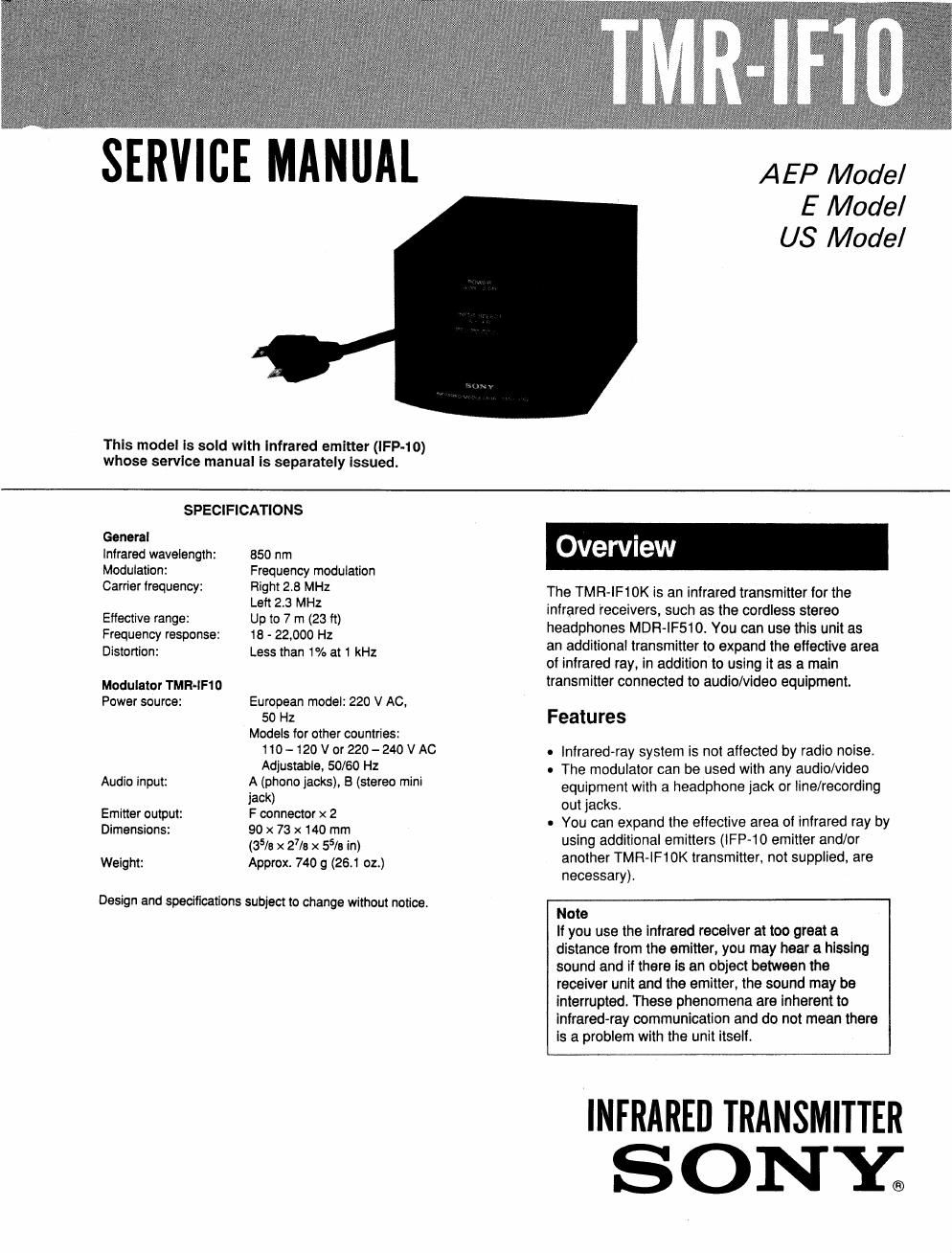
Sony tmr if 10 service manual

This is the 9 pages manual for sony tmr if 10 service manual.
Read or download the pdf for free. If you want to contribute, please mail your pdfs to info@audioservicemanuals.com.

Page: 1 / 9
left right
sony tmr if 10 service manual

Extracted text from sony tmr if 10 service manual (Ocr-read)


Page 1

SERVICE MANUAL

This model Is sold with Infrared emitter (IFP-10)
whose service manual ls separately Issued.

AEP Model
E Model
US Model

SPECIFICATIONS
General
Infrared wavelength: 850 nm
Modulation: Frequency modulation
Carrier frequency: Flight 28 MHz

Left 2.3 MHz

Effective range: Up to 7 m (23 ft)
Frequency response: 18 - 22,000 Hz
Distortion: Less than 1% at 1 kHz

Modulator TMFI-lFlO
Power source: European model: 220 V AC,
50 Hz
Models for other countries:
110- 120 V or 220-240 V AC
Adjustable, 50/60 Hz

Audio input: A (phone jacks), B (stereo mini
jack)

Emitter output: F connector x 2

Dimensions: 90 x 73 x 140 mm
(35/3 x 27/! x 55/3 in)

Weight: Approx. 740 g (26.1 02.)

Design and specifications subject to change without notice.

Overview

The TMR-IF10K is an infrared transmitter for the
infrared receivers. such as the cordless stereo
headphones MDFt-lF510. You can use this unit as
an additional transmitter to expand the effective area
of infrared ray, in addition to using it as a main
transmitter connected to audio/video equipment.

Features

. |nfrared»ray system is not affected by radio noise.

0 The modulator can be used with any audio/video
equipment with a headphone jack or line/recording
out jacks.

- You can expand the effective area of infrared ray by
using additional emitters (IFP-10 emitter and/or
another TMFl-IF10K transmitter. not supplied, are
necessary).

Note

If you use the infrared receiver at too great a
distance from the emitter, you may hear a hissing
sound and if there Is an object between the
receiver unit and the emitter, the sound may be
interrupted. These phenomena are inherent to
Infrared-ray communication and do not mean there
Is a problem with the unit itself.

INFRARED TRANSMITTER
S ONY.

Page 2

SAFETY CHECK-OUT

After correcting the original service problem,
perform the following safety check before releasing
the set to the customer:

Check the antenna terminals, metal trim, metallized
knobs, screws, and all other exposed metal parts for
AC leakage. Check leakage as described below.

LEAKAGE TEST

The AC leakage from any exposed metal part to
earth ground and from all exposed metal parts to any
exposed metal part having a return to chassis, must
not exceed 0.5 mA (500 microampers). Leakage
current can be measured by any one of three
methods.

I. A commercial leakage tester, such as the
Simpson 229 or RCA WT-S40A. Follow the
manufacturers' instructions to use these instru-
moms.

to

A battery-operated AC milliammeter. The Data
Precision 245 digital multimeter is suitable for
this job.

3. Measuring the voltage drop across a resistor by
means of a VOM or battery-operated AC volt-
meter. The limit" indication is 0.75V, so
analog meters must have an accurate low-
voltage scale. The Simpson 250 and Sanwa
SH-63Trd are examples of a passive VOM that
is suitable. Nearly all battery operated digital
multimeters that have a 2V AC range are
suitable. (See Fig. A)

To Exposed Metal
Part: on Set

AC
0.15uF glokiz voltmeter
{0.75 V}

'é' Earth Ground

Fig. A. Using an AC voltmeter to check AC leakage.

SA FETY»R E LATED COMPONENT WARN INGI!

COMPONENTS IDENTIFIED BV MARK A OR DOTTED
LINE WITH MARK A ON THE SCHEMATIC DIAGRAMS
AND IN THE PARTS LIST ARE CRITICAL TO SAFE
OPERATION. REPLACE THESE COMPONENTS WITH
SONY PARTS WHOSE PART NUMBERS APPEAR AS
SHOWN IN THIS MANUAL OR IN SUPPLEMENTS PUB-
LISHED BY SONY.

SECTION 1
GENERAL

LOCATION AND FUNCTION OF CONTROLS

Modulator


Mowuron
uoDE

MAIN -
sue -

[I] MODULATOR MODE switch
Set the switch according to the table below. If It
Is not'set properly, no sound will be output.

when ".5"9 as a Set the switch to MAIN
maln Unll

Set the switch on the
modulator connected to

When "5an as an audio/video equipment to

additional UIIiI MAIN, and'tho switch on
the other modulator to
SUB.

[Z] POWER switch
Press to turn on the modulator and the emitter.

When they are turned on, the switch glows
green. To turn oft. press it again.

[E] INPUT SELECT switch
Selects the equipment connected to AUDIO IN A

or B jacks.

E SOUND MODE switch
Set to A or B in accordance with the type oi your

receiver.

[3 AUDIO m jacks
A-phono jacks B-stereo mini jack