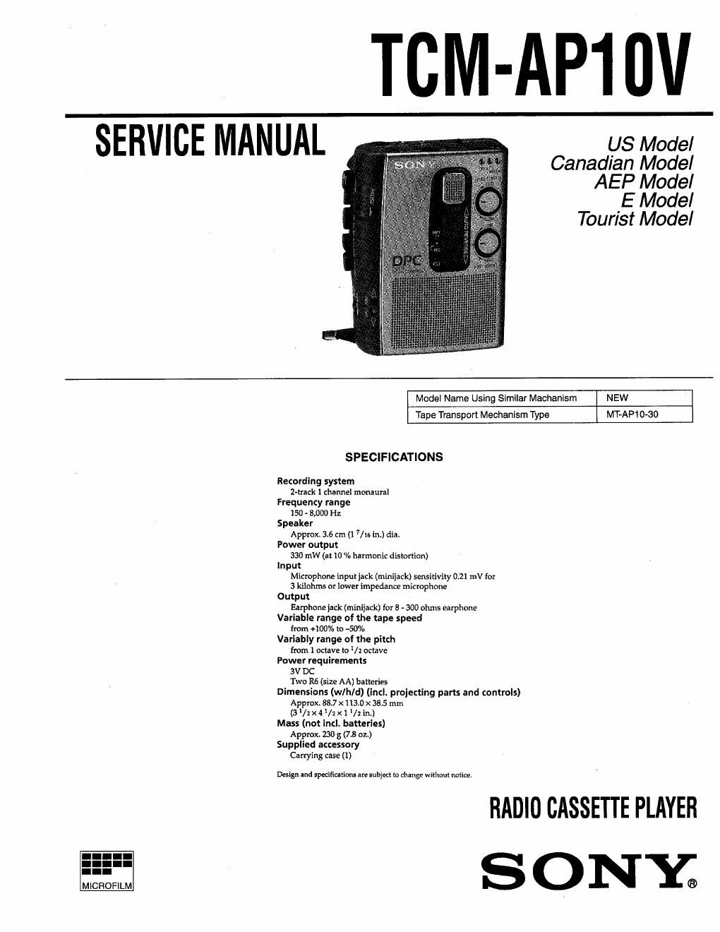
Sony tcm ap 10 v service manual

This is the 13 pages manual for sony tcm ap 10 v service manual.
Read or download the pdf for free. If you want to contribute, please mail your pdfs to info@audioservicemanuals.com.

Page: 1 / 13
left right
sony tcm ap 10 v service manual

Extracted text from sony tcm ap 10 v service manual (Ocr-read)


Page 1

CM;_l_lP10V

US Model
Canadian Model
AEP Model

E Model

Tourist Model

Model Name Using Similar Mechanism NEW
Tape Transport Mechanism Type MT-AP10-30
SPECIFICATIONS

Recording system
Z-track 1 channel monaural
Frequenzy range
150 - 8,000 Hz
Speaker
Appmxl 36 cm (1 7/u3 In.) dia.
Power output
330 mW (at IO (a harmonic distortion)
Input
Microphone inputiack (miniiack) sensitivity 0.2! mV for
3 kilohms or lower impedance microphone
Output
Earphone jack (minifack) for 8 - 300 ohms earphone
Variable range of the tape speed
from +IOD% to 430%
Variably range of the pitch
from 1 octave to /2 Oclave
Power requirements
3V DC
Two R6 (size AA) batteries
Dimensions (w/h/d) (incl. projecting parts and controls)
Approx. 38.7 x 113.0 X 38.5 mm
(3 lzx 4/1x1/1 in.)
Mass (not incl. batteries)
Approx. 230 g (7.8 oz)
Supplied accessory
Carrying case (1)

DesIgn and specifiral'imu are subject to change withoul notice.

RADIO CASSETTE PLAYER

SONY;

Page 2

TABLE OF CONTENTS

Flexible Clrcult Board Repairing ' Specifications .............................................................................. 1
0 Keep the» temperature of the soldering iron around 270°C during '
repairing. 1. GENERAL
Location and Function of Controls ....................................... 2

0 Do not touch the soldering iron on the same conductor of the cir-
cuit board (within 3 times).

0 Be careful not to apply force on the conductor when soldering or
unsoldering. >

2. SERVICING NOTES .. ...... 3

3. DISASSEMBLY ................................................................... 4

Notes on chip component replacement

0 Never reuse a disconnected chip component.

0 Notice that the minus side of a tantalum capacitor may be dam-
aged by heat:

4. MECHANICAL ADJUSTMENTS ............................. 6

5. ELECTRICAL ADJUSTMENTS ....................................... 6

6. DIAGRAMS
6-1. Block Diagram ..........
6-2. Printed Wiring Boards ..
6-3. Schematic Diagram ....................................................... 15

7. EXPLODED VIEWS
7-]. Cabinet Section ....................
7-2. Mechanism Deck Section (1) ..
7-3. Mechanism Deck Section (2) ..

8. ELECTRICAL PARTS LIST ............................................ 23

SECTION 1
GENERAL

LOCATION AND FUNCTION OF CONTROLS This 590" is 9Xiracted lrum
instruction manual.

TAPE counter
EARPHONE jack
MICROPHONE jack
VOLUME knob

PAUSE button

0 REC button

I STOP button

PLAY button
HEW/REVIEW button
FF/CUE button

DIR -k button
REV/FWD indicator
VOR switch

DPC switch

DPC POSITION indicator
FLAT MICROPHONE
SPEED CONTROL knob
PITCH CONTROL knob
BATT/REC lamp

BATT CHANGE lamp
SPEAKER

15

U'I-thiM-l

17

_.
DEQQQEEBQEMEJH E Mitllflllflllzl

:mmuflaa
"Lal

e
EIBJ