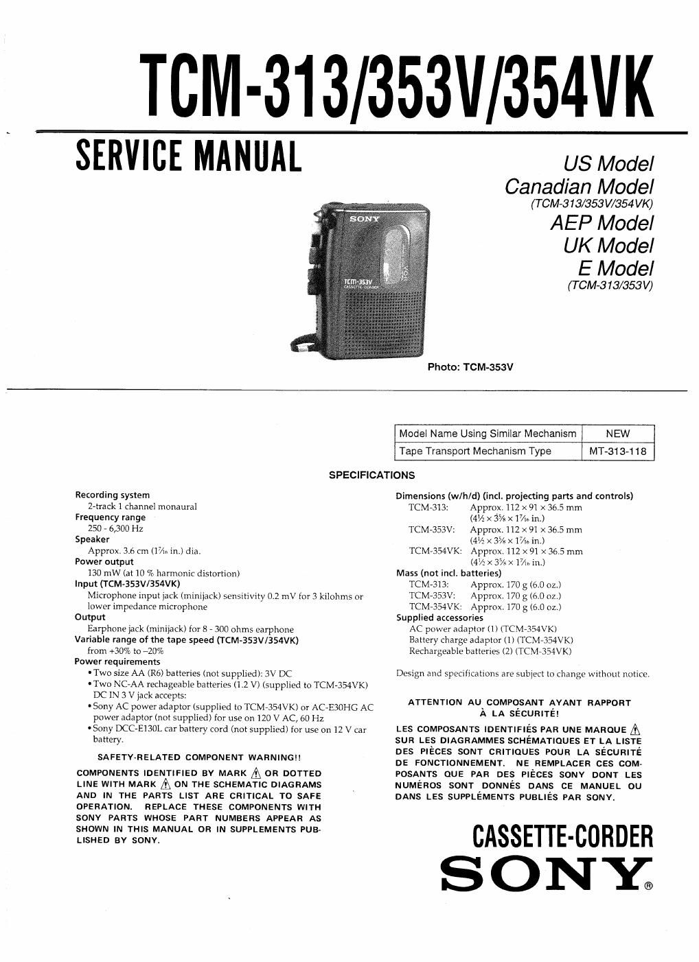
Sony tcm 353 v service manual

This is the 14 pages manual for sony tcm 353 v service manual.
Read or download the pdf for free. If you want to contribute, please mail your pdfs to info@audioservicemanuals.com.

Page: 1 / 14
left right
sony tcm 353 v service manual

Extracted text from sony tcm 353 v service manual (Ocr-read)


Page 1

TCM-313/353V/354VK

SERVICE MANUAL

US Model
Canadian Model

(T CM-3 13/353 W354 VK)

AEP Model
UK Model
E Model

(T CM-313/353V)
Photo: TOM-353V
Model Name Using Similar Mechanism NEW
Tape Transport Mechanism Type MT-313-118

SPECIFICATIONS

Recording system
2-track1 channel monaural
Frequency range
250 - 6,300 HZ
Speaker
Approx. 3.6 cm (Ii/in int) dia.
Power output
130 mW (at 10 % harmonic distortion)
Input (TCMv353V/354VK)
Microphone input jack (minijack) sensitivity 0.2 mV for 3 kilohms or
lower impedance microphone
Output
Earphone jack (minijack) for 8 - 300 ohms earphone
Variable range of the tape speed (TCM-353Vl354VK)
from +30% to ~20%
Power requirements
'Two size AA (R6) batteries (not supplied): 3V DC
- Two NCAAA rechageable batteries (12 V) (supplied to TCM»354VK)
DC IN 3 V jack accepts:
' Sony AC power adaptor (supplied to TCM~354VK) or AC-E3OHG AC
power adaptor (not supplied) for use on 120 V AC, 60 Hz
'Sony DCC-E130L car battery cord (not supplied) for use on 12 V car
battery.

SAFETYvRELATED COMPONENT WARNING

COMPONENTS IDENTIFIED BY MARK A OR DOTTED
LINE WITH MARK A ON THE SCHEMATIC DIAGRAMS
AND IN THE PARTS LIST ARE CRITICAL TO SAFE
OPERATION. REPLACE THESE COMPONENTS WITH
SONY PARTS WHOSE PART NUMBERS APPEAR AS
SHOWN IN THIS MANUAL OR IN SUPPLEMENTS PUB-
LISHED BY SONY.

Dimensions (w/h/d) (incl. projecting parts and controls)
TCM-313: Approx. 112 X 91 x 36.5 mm
(4V2 X 3% X 17/I61n)
TCM-353V: Approx. 112 X 91 X 36.5 mm
(4% X 3% X 17m in.)
TCM-354VK: Approx. 112 X 91 X 36.5 mm
(4% x 3% X 17/». in.)
Mass (not incl. batteries)
TCM-313: Approx. 170 g (6.0 oz.)
TCM-353V: Approx. 170 g (6.0 oz.)
TCM-354VK: Approx, 170 g (610 oz.)
Supplied accessories
AC power adaptor (1) (TCM-354VK)
Battery charge adaptor (1) (TCM-354VK)
Rechargeable batteries (2) (TCM-354VK)

Design and specifications are subject to change without notice.

ATTENTION AU COMPOSANT AYANT RAPPORT

A LA sécumré!

LES COMPOSANTS IDENTIFIES PAR UNE MAROUE A
sun LES DIAGRAMMES SCHEMATIQUES ET LA LISTE
DES PIECES soNr CRITIQUES POUR LA sécunlré
DE FONCTIONNEMENT. NE REMPLACER css com-
POSANTS QUE PAR DES PIECES sonv DONT LES
NUMEROS SONT DONNES DANS CE MANUEL ou
DANS LES SUPPLEMENTS PUBLIES PAR sonv.

CASSETTE-BORDER
S O N Y.

Page 2

TABLE OF CONTENTS

@122 M 112g;

Specifications .................................. 1
GENERAL ............................. 2

2. DISASSEMBLY ------------------------- Z

3. MECHANICAL ADJUSTMENTS ~~~~~~~~~ 3

4. ELECTRICAL ADJUSTMENTS ---------- 4

5. DIAGRAMS

5-1. Block Diagram ------

52. Printed Wiring Boards -

5-3. Schematic Diagram

6. EXPLODED VIEWS

7. ELECTRICAL PARTS LIST ------------ 17

Flexible Circult Board Repalrlng

Keep the temperature of the soldering iron around
270°C during repairing.

Do not touch the soldering iron on the same conductor
of the circuit board (within 3 times).

Be careful not to apply force on the conductor when
soldering or unsoldering.

Notes on chlp component replacement

0
I

Never reuse a disconnected chip component,
Notice that the minus side of a tantalum capacitor may
be damaged by heat.

SECTION 1
GENERAL

Parts ldentiflcatlon

SPEED CONTROL

« REW/ REVIEW

Built-In
microphone

C REC
I STOP

D PLAY

» FF/CUE

PAUSE -b~

SECTION 2
DISASSEMBLY

Note: Follow the disassembly procedure in the numerical order given,
REAR CABINET, CASSETTE LID

0 two hinge plate

Q two cords
(SPQOI)

6 rear cabinet

0 screw (1.4 X 5.0)

0 claw 0 Egrfigfcrews
MAIN BOARD, MECHANISM DECK

0 two screws (P1l4 X 3.0)

6 two oords
(Mlcsoi)

9 two cords
, (M901)

l

0 screw

é/(MJ >< 5)

(3 MAIN board

9 screw (M1.4)