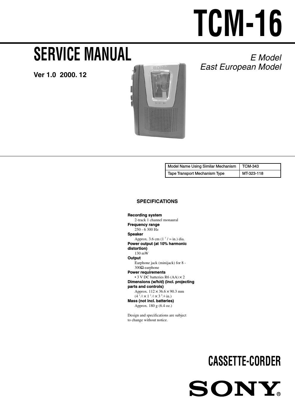
Sony tcm 16 ver 1 0 cassette corder

This is the 15 pages manual for sony tcm 16 ver 1 0 cassette corder.
Read or download the pdf for free. If you want to contribute, please mail your pdfs to info@audioservicemanuals.com.

Page: 1 / 15
left right
sony tcm 16 ver 1 0 cassette corder

Extracted text from sony tcm 16 ver 1 0 cassette corder (Ocr-read)


Page 1

- 2 - Notes on chip component replacement -Never reuse a disconnected chip component. -Notice that the minus side of a tantalum capacitor may be damaged by heat. Flexible Circuit Board Repairing -Keep the temperature of soldering iron around 270˚C during repairing. -Do not touch the soldering iron on the same conductor of the circuit board (within 3 times). -Be careful not to apply force on the conductor when soldering or unsoldering. TABLE OF CONTENTS 1. GENERAL ··········································································2 2. DISASSEMBLY 2-1. Lid Sub Assy, Cassette····················································3 2-2. Main Board, Mechanism Deck·······································3 2-3. Belt··················································································4 2-4. Head, Magnetic, Pinch Roller·····································4 3. MECHANICAL ADJUSTMENT ··································5 4. ELECTRICAL ADJUSTMENT ····································5 5. DIAGRAMS 5-1. IC Block Diagram···························································6 5-2. Block Diagram································································7 5-3. Schematic Diagram·························································9 5-4. Printed Wiring Board····················································11 6. EXPLODED VIEWS 6-1. Cabinet Section·····························································13 6-2. Mechanism Deck Section-1 (MT-323-118)··················14 6-3. Mechanism Deck Section-2 (MT-323-118)··················15 7. ELECTRICAL PARTS LIST ·······································16 SECTION 1 GENERAL This section is extracted from instruction manual. VOL M FF/CUE x STOP m REW/REVIEW PAUSE . N PLAY EAR z REC x STOP m REW/ REVIEW PAUSE . Built-in mic Micrófono incorporado Microfone incorporado BATT

Page 2

- 3 - SECTION 2 DISASSEMBLY Note :Follow the disassembly procedure in the numerical order given. - The equipment can be removed using the following procedure. 2-1. LID SUB ASSY, CASSETTE 2-2. MAIN BOARD, MECHANISM DECK 4 two cords(SP901) 6 spring, cassett e 5 lid sub assy, cassette four claws claw 3 cabinet (rear) 2 screw (IB LOCK) 1 three screws (B1.7 × 9) 8 mechanism deck 6 main board 4 cord (HRP901) 5 two cords (MIC901) 3 two cords (M901) 1 screw (1.7) 2 screw (M1.4) 7 three screws (IB LOCK) Lid Sub Assy, Cassette Main Board, Mechanism Deck Belt Set Head, Magnetic, Pinch Rolle r