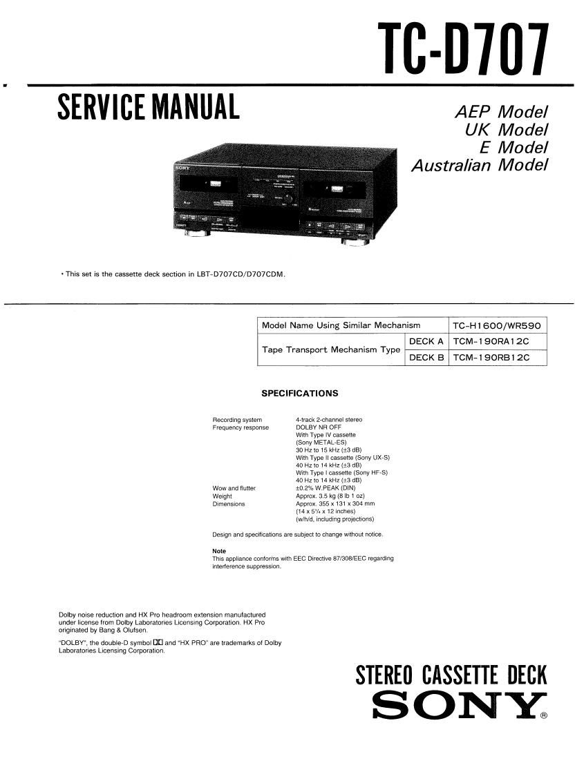
Sony TCD 707 Service Manual

This is the 28 pages manual for Sony TCD 707 Service Manual.
Read or download the pdf for free. If you want to contribute, please mail your pdfs to info@audioservicemanuals.com.

Page: 1 / 28
left right
Sony TCD 707 Service Manual

Extracted text from Sony TCD 707 Service Manual (Ocr-read)


Page 1

TC-D'Ill'l

SERVICE MANUAL AEP Model

UK Model
E Model
Australian Model

' This set is the cassette deck section in LBT-D707CD/D707CDM.

Model Name Using Similar Mechanism TC-Hl 600/WR590
DECK A TOM-190RA12C
DECK B TOM-190RB12C

Tape Transport Mechanism Type

SPECIFICATIONS
Recording sysiern 4~track 2-channel stereo
Frequency response DOLBY NR OFF

With Type IV cassette

(Sony METALES)

30 Hz to 15 kHz (:3 dB)

With Type II cassette (Sony UX-S)
40 HZ lo 14 kHZ (:3 dB)

With Type I cassette (Sony HF-S)
40 Hz to 14 kHz (13 dB)

Wow and flutter 10.2% W.PEAK (DIN)
Weight Approx 315 kg (8 lb 1 oz)
Dimensions Approx 855 x 131 x 304 mm

(14 x 5% x 12 inches)
(w/h/d, Including projections)

Design and specifications are subject to change Without notice.

Note
This appliance conforms with EEC Directive 87/308/EEC regarding
interference suppression.

Dolby noise reduction and HX Pro headroom extension manufactured
under license from Dolby Laboratories Licensing Corporation, HX Pro
originated by Bang & Olulsen,

DOLBY, the double-D symbol DD and HX PRO" are trademarks oi Dolby
Laboratories Licensmg Corporation

STEREII CASSETTE DECK

SONYQ

Page 2

TC-D707

Section
SECTION 1.

SECTION 2.

SECTION 3.
3-1.
3-2.

SECTION 4.
4-1.
4.2.
43.
4-4.

4~5.
4-6,

SECTION 5.
5-1.
5-2.
5-3.
5-4.

SECTION 6.

TABLE OF CONTENTS

Title Page
GENERAL
DISASSEMBLY ............................................. 4
ADJUSTMENTS
Mechanical Adjustments ...................... 6
Electrical Adjustments .......................................... 6
DIAGRAMS

Cimuil Boards Location > 10
- 11

~12

Semiconductor Lead Layouts ~
Printed Wiring Boards-Main Section-

Schematic Diagrams-Main Secfion- .. 17
[C Block Diagrams ............................................. 21
Printed Wiring Boards-Panel Seclion-""m-mw'm 21
Schematic Diagrams-Panel Secu'on- --------------------- 23
EXPLODED VIEWS

Overall Section ................................................... 25
Front panel Section ..... . ....................................... 26
Mechanism Section-1 .......................................... 27
Mechanism SecfiOn_2 .......................................... 23

ELECTRICAL PARTS LIST

~ 29

SAFETY-RELATED COMPONENT WARNING

COMPONENTS IDENTIFIED BV MARK A OR DOTTED
LINE WITH MARK A ON THE SCHEMATIC DIAGRAMS
AND IN THE PARTS LIST ARE CRITICAL TO SAFE
OPERATION. REPLACE THESE COMPONENTS WITH
SONY PARTS WHOSE PART NUMBERS APPEAR AS
SHOWN IN THIS MANUAL OR IN SUPPLEMENTS PUB-
LISHED BY SONY.