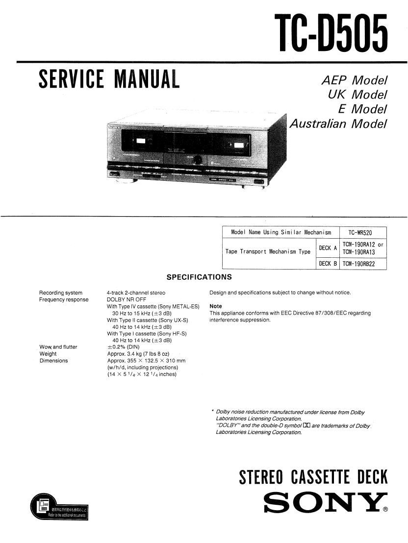
Sony TCD 505 Service Manual

This is the 26 pages manual for Sony TCD 505 Service Manual.
Read or download the pdf for free. If you want to contribute, please mail your pdfs to info@audioservicemanuals.com.

Page: 1 / 26
left right
Sony TCD 505 Service Manual

Extracted text from Sony TCD 505 Service Manual (Ocr-read)


Page 1

Til-0505

SERVICE MANUAL AEP Moder

UK Model
E Model
Australian Model

Recording system
Frequency response

Wow and flutter
Weight
Dimensions

Mode! Name Using Similar Mechanism TC-WR520

TCM-IQORAIZ or
Tape Transport Mechanism Type DECK A TCM-190RA13

DECK B TOM-190M322

SPECIFICATIONS
4-track 2-channel stereo Design and specifications subject to change without notice
DOLBY NR OFF
With Type IV cassette (Sony METALAES) Note
30 Hz to 15 kHz (:3 dB) This appiianoe conforms with EEC Directive 87/308/EEC regarding
With Type II cassette (Sony UX-S) interference suppression,

40 H2 to 14 kHz ($3 1218)
With Type 1 cassette (Sony HF-S)
40 Hz to 14 kHz (:8 dB)
:02% (DIN)
Approx. 34 kg (7 lbs 8 oz)
Approx. 355 X 132.5 X 310 mm
(win/d, including projections)
(14 X 5/4v>< 121/4 inches)

' Dolby noise reduction manulactured under license from Dolby
Laboratories Licensing Corporation
DOLBY" and the double-D symbol DC are trademarks of Dolby
Laboratories Licensing Corporation

STEREU CASSETTE DECK
SONE

Page 2

TC-D505

SAFETY CH ECK-OUT

After correcting the original service problem,
perform the following safety check before releasing
the set to the customer:

Check the antenna terminals, metal trim, metallized
knobs, screws, and all other exposed metal parts for
AC leakage. Check leakage as described below.

LEAKAGE TEST

The AC leakage from any exposed metal part to
earth ground and from all exposed metal parts to any
exposed metal part having a return to chassis, must
not exceed 0.5 mA (500 microampers). Leakage
current can be measured by any one of three
methods

l. A commercial leakage tester, such as the
Simpson 229 or RCA WT-S40A. Follow the
manufacturers instructions to use these instrU-
ments.

2. A battery~operated AC milliammeter. The Data
Precision 245 digital multimeter is suitable for
this job,

3. Measuring the voltage drop across a resistor by
means of a VOM or battery-operated AC volt-
meter. The limit" indication is 0.75V. so
analog meters must have an accurate low-
voltage scale. The Simpson 250 and Sanwa
SH-63Trd are examples of a passive VOM that
is suitable. Nearly all battery operated digital
mUItimeters that have a 2V AC range are
suitable (See Fig A)

To Exposed Metal
Pairs on Set

AC
/ valtmera/
(0.75 V)

0J5MF IELSHT
L.

9: Earth Ground

Fig A. Using an AC voltmeter to check AC leakage,

TABLE OF CONTENTS

Section Title Pye
SECTION I. GENERAL- ~ - o - - ~ . . . ~ ~ 3
SECTION 2. DISASSEMBLY' . ~ ~ - - ~ . . . 4
SECTION 3. MECHANICAL ADJUSTMENTS ~ ' . ~ 5
SECTION 4. ELECTRICAL ADJUSTMENTS - ~ ~ . 5
SECTION 5. DIAGRAMS

5-14 Printed Wiring Boards

-Main Section-e - ~ . « ~ ~ ~ . 9

5-2. Schematic Diagram

-Main Section- - ~ . - . . . 0 '13

5-3. Circuit Boards Location- . .17

5-4. Printed Wiring Boards

-Pane1 Section- . ~ ~ ~ . . - ~17

5-5. Schematic Diagram

-Pane1 Section- - - . ~ . . . '19
SECTION 6. EXPLODED VIEWS

6-1. Chassis Section- . - . - . -21

6-2. Front Panel Section. ~ ~ . - 22

8-3. Mechanism Section 1» ~ ~ ~ ~23

6-4. Mechanism Section 2' - . ~ .24
SECTION 7. ELECTRICAL PARTS LIST. . . -25

SAFETY-RELATED COMPONENT WARNING]!

COMPONENTS IDENTIFIED BY MARK A OR DOTTED
LINE WITH MARK A ON THE SCHEMATIC DIAGRAMS
AND IN THE PARTS LIST ARE CRITICAL TO SAFE
OPERATION. REPLACE THESE COMPONENTS WITH
SONY PARTS WHOSE PART NUMBERS APPEAR AS
SHOWN IN THIS MANUAL OR IN SUPPLEMENTS PUB-
LISHED BV SONY.