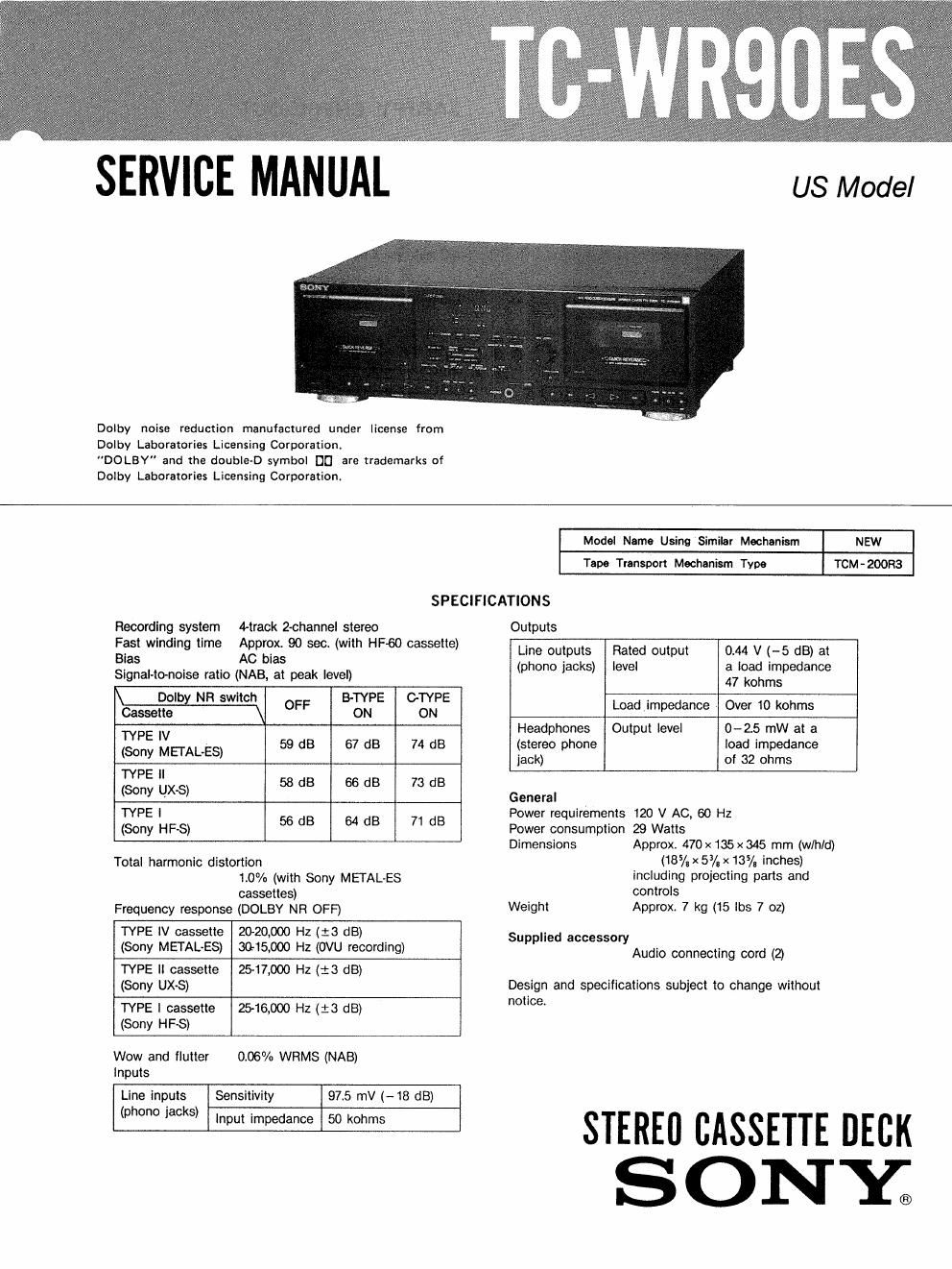
Sony tc wr 90 es service manual

This is the 26 pages manual for sony tc wr 90 es service manual.
Read or download the pdf for free. If you want to contribute, please mail your pdfs to info@audioservicemanuals.com.

Page: 1 / 26
left right
sony tc wr 90 es service manual

Extracted text from sony tc wr 90 es service manual (Ocr-read)


Page 1

SERVICE MANUAL

US Model

Dolby noise reduction manufactured under license from
Dolby Laboratories Licensing Corporation.
DOLBY" and the double-D symbol DC] are trademarks of
Dolby Laboratories Licensing Corporation.

Recording system 4-track Zchannel stereo
Fast winding time Approx. 90 sec. (with HFoO cassette)
Bias AC bias
Signal-to-noise ratio (NAB, at peak level)

Model Name Using Similar Mechanism NEW

Tape Transport Mechanism Tym TCM-200R3

SPECIFICATIONS

M OFF BrTYPE GTYPE
Cassette ON ON

(T8175! IIIIETAHES) 59 dB 67 dB 74 dB
(2:; IIJX-S) 53 dB 66 dB 73 dB
{51:5, Luis) 56 dB 64 dB 71 dB

Total harmonic distortion

10% (with Sony MEIAL-ES
cassettes)
Frequency response (DOLBY NR OFF)

TYPE IV cassette 2020,000 Hz (:3 dB)
(Sony METAL-ES) aft-15,000 Hz (OVU recording)

(Sony UX-S)

TYPE II cassette 25-11000 Hz (1'3 dB)

(Sony HFS)

TYPE I cassette 2516,000 Hz (:3 dB)

Inputs

Wow and flutter 0.05% WRMS (NAB)

Line inputs Sensitivity

97.5 mV (-18 dB)

(phono jacks)

Input impedance

50 kohms

Outputs
Line outputs Rated output 0.44 V (--5 dB) at
(phono jacks) level a load impedance
47 kohms

Load impedance Over 10 kohms
Headphones Output level 0-2.5 mW at a
(stereo phone load impedance
lack) of 32 ohms

General

Power requirements 120 V AC, 60 Hz
Power consumption 29 Watts
Approx. 470x135x345 mm (w/hld)
(185/a x 53/,x13/. inches)
including projecting parts and

Dimensions

Weight

controls

Approx. 7 kg (15 lbs 7 oz)

Supplied accessory

Audio connecting cord (2')

Design and specifications subject to change without

notice.

STEREI] cAssmE DECK
ONE

Page 2

TC-WRQOES I

TABLE OF CONTENTS

Section Title Page
Specificationsmv'mum-mun 1
Features... ....... ........ .............. u ......... . 2
1. GENERAL
Identification of Front Panel Parts ------------- 3
2. DISASSEMBLY 4
3. ELECTRICAL ADJUSTMENTS
8-1. Mechanical Adjustments 7
3-2. Electrical Adjustments ------------------ 7
4. DIAGRAMS
4- 1. Semiconductor Lead Layouts ------------- ~~~11
4-2. Circuit Boards Location .. ------------------- 12
4-3.1(3 Block Diagram............................13
4-4. Printed Wiring Boards-"N" W14
4-5. Schematic Diagram- ~ ~
5. EXPLODED VIEWS ................................ 27
6, ELECTRICAL PARTS LIST ........................ 31

Features

. The Dolby HX PRO= system which improves the
linearity at a tapes high-range response during
recording.

0 Automatic recording level adjustment for one touch
protection against distortion.

0 A relay function for long recording and playback.

- Quick reversing at the end of a tape to minimize
interruptions during playback and recording.

0 Fade-in and fade-out lunctlons to start and end
recordings with a protessional touch.

- Auto-synchro dubbing at normal or high (double)
speed.

0 AMS and memory play functions which provide easy
access to desired selections.

0 An easy-to-read linear counter which shows the
elapsed recording or playback time for decks A and B.

t Dolby noise reduction and HX Pro headroom extension manufactured
under license lrorn Dolby Laboratories Licensing Corporallon. HX Pro
originated by Bang & Olulsen.

DOLEV. the double-D symbol DI] and "HX PRO" are trademarks
of Dolby Laboratories Licensing Corporation.

SAFETY CHECK-OUT

After correcting the original service problem,
perform the following safety check before releasing
the set to the customer:

Check the antenna terminals, metal trim, metallized
knobs, screws, and all other exposed metal parts for
AC leakage. Check leakage as described below.

LEAKAGE TEST

The AC leakage from any exposed metal part to
earth ground and from all exposed metal parts to any
exposed metal part having a return to chassis, must
not exceed 0.5 mA (500 microampers). Leakage
current can be measured by any one of three
methods.

I. A commercial leakage tester, such as the
Simpson 229 or RCA WTv540A. Follow the
manufacturers instructions to use these instru-

ments.

2. A battery-operated AC milliammeter. The Data
Precision 245 digital multimeter is suitable for
this job.

3. Measuring the voltage drop across a resistor by

means of a VOM or batteryoperated AC volt-
meter. Thc limit" indication is 0.7SV, so
analog meters must have an accurate low-
voltage scale. The Simpson 250 and Sanwa
SH-63Trd are examples of a passive VOM that
is suitable. Nearly all battery operated digital
multimeters that have a 2V AC range are
suitable. (See Fig. A)

To Exposed Metal
Part: on Set

A C
voltmeter

0.15uF
(075 VI

r
-‚¬15 kt) /
L.

Earth Ground

Fig. A. Using an AC voltmeter to check AC leakage.

SAFETY-RELATED COMPONENT WARNINGII

COMPONENTS IDENTIFIED BY MARK A OR DOTTED
LINE WITH MARK A ON THE SCHEMATIC DIAGRAMS
AND IN THE PARTS LIST ARE CRITICAL T0 SAFE
OPERATION. REPLACE THESE COMPONENTS WITH
SONY PARTS WHOSE PART NUMBERS APPEAR AS
SHOWN IN THIS MANUAL OR IN SUPPLEMENTS PUB-
LISHED BY SONY.