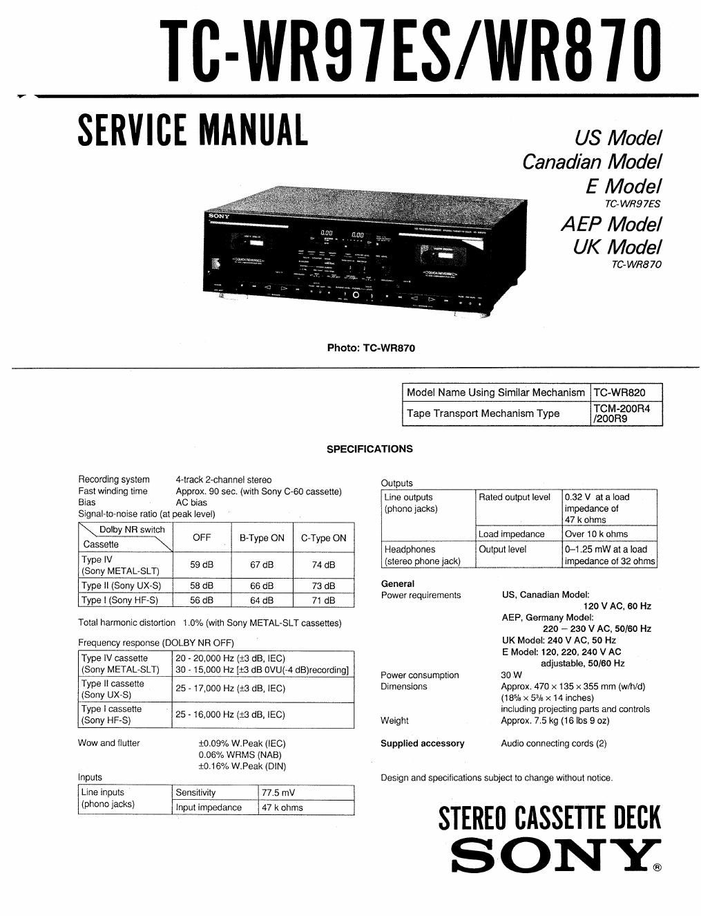
Sony tc wr 870 service manual 2

This is the 31 pages manual for sony tc wr 870 service manual 2.
Read or download the pdf for free. If you want to contribute, please mail your pdfs to info@audioservicemanuals.com.

Page: 1 / 31
left right
sony tc wr 870 service manual 2

Extracted text from sony tc wr 870 service manual 2 (Ocr-read)


Page 1

TC-WRB'IES/WRB'ID

SERVICE MANUAL

US Model
Canadian Model
E Model

TC- WHQ 758

A EP Model
UK Model

TC'WR870
Photo: TC-WR870
Model Name Using Similar Mechanism TC»WR820
Tape Transport Mechanism Type Lglgézgoomt
SPECIFICATIONS
Recording system rack 2-channel stereo Outputs
Fast winding time Approx 90 sec. (with Sony 0-60 cassette) Line out uts Rated out ut level 0 32 V at a I o a d
Bias Ac bias n P k p in; d {
Signal-tovnoise ratio (at peak level) (p ono gac S) fox: 0
Dell) NR switch .
C -tty- OFF BType ON C-Type ON Load Impedance Over 10 k ohms
asse e Head hones Output level 0-1.25 mW ata load
P
Type IV (stereo phone jack) impedance of 32 ohms
(Sony METAL-8LT) 59 dB 67 dB 74 dB
Type in (Sony UX-S) 53 dB 66 dB 73 dB General _ .
Type I (Sony HF-S) 56 dB 84 dB 71 (:18 Power requirements US, Canadian Model.

Total harmonic distortion 1.0% (with Sony METAL-8LT cassettes)

Frequency response (DOLBY NFI OFF)

Type IV cassette

20 » 20,000 Hz (1-3 dB, IEC)

(Sony METAL-8LT) 30 - 15,000 Hz [:3 dB OVU(-4 dB)recording]
Type II cassette _

(Sony UX»S) 25 17,000 Hz (:3 dB, IEC)

Type I cassette _

(Sony HF-S) 25 16,000 Hz (:3 dB, IEC)

Wow and ilutter

10.09% W.Peak (IEC)
006% WRMS (NAB)
10.16% W.Peak (DIN)

Inputs
Line inputs Sensitivity 77.5 mV
(phono 13°) lnput impedance 47 k ohms

Power consumption
Dimensions

Weight

Supplied accessory

120 V AC, 60 Hz

AEP, Germany Model:
220 -- 230 V AC, 50/60 Hz
UK Model: 240 V AC. 50 Hz
E Model: 120. 220. 240 V AC
adjustable, 50/60 Hz

30W

Approx. 470 x 135 x 355 mm (w/h/d)
(18% x 5% x 14 inches)

including projecting parts and controls
Approx. 7.5 kg (16 lbs 9 oz)

Audio connecting cords (2)

Design and specifications subject to change without notice.

STEREO CASSETTE DECK
SONSC.

Page 2

TC-WR97ES/\NR87O

TABLE OF CONTENTS

Section M Page
Specifications .................................. 1
Model Identification ............................ 2
Safety Check-out ............................... 2
1. GENERAL
Identification of Front Panel Parts ~~~~~~~~~~~ 3
Connections ............................. 4
2. DISASSEMBLY ......................... 5
3. ADJUSTMENTS
3-1 Mechanical Adjustments ~~~~~~~~~~~~~~~~~~~ g
32. Electrical Adjustment --------------------- 8
4. DIAGRAMS
4.1. Block Diagram .......................... 12
4-2. Printed Wiring Boards ........... . 16
4.3, Schematic Diagram ....................... 21
5. EXPLODED VIEWS .................... 29
6. ELECTRICAL PARTS LIST ------------ 33

MODEL IDENTIFICATION
- Specification Label -

TC-WR97ES
TC-WR87O

MODEL No. m

STEREO CASSETTE DECK

/////////////////////////%

SERIAL No.
MADE IN JAPAN

AC: 120V 60Hz 30W
AC: 220 - 230V~50l60 HZ
AC: 240 V~5O Hz

US, Canadian Model:
Germany, AEP Models:
UK Model:

E Model:

SA FETY-RE LATED COMPONENT WARNI NGII

COMPONENTS IDENTIFIED BY MARK A OH DOTTED
LINE WITH MARK A ON THE SCHEMATIC DIAGRAMS
AND IN THE PARTS LIST ARE CRITICAL TO SAFE
OPERATION. REPLACE THESE COMPONENTS WtTH
SONY PARTS WHOSE PART NUMBERS APPEAR AS
SHOWN IN THIS MANUAL OR IN SUPPLEMENTS PUB-
LISHED BY SONY.

AC: 120, 220, 240 V~50l60 HZ 30W

SAFETY CH EC K-OUT

After correcting the original service problem,
perform the following safety check before releasing
the set to the customer:

Check the antenna terminals, metal trim, metallized
knobs, screws, and all other exposed metal parts for
AC leakage, Check leakage as described below.

LEAKAGE TEST

The AC leakage from any exposed metal part to
earth ground and from all exposed metal parts to any
exposed metal part having a return to chassis, must
not exceed 0.5 mA (500 microampers). Leakage
current can be measured by any one of three
methods.

I. A commercial leakage tester, such as the
Simpson 229 or RCA WT-540A. Follow the
manufacturers instructions to use these instru-
ments.

2. A battery-operated AC milliammeter. The Data
Precision 245 digital multimeter is suitable for
this job.

3. Measuring the voltage drop across a resistor by
means of a VOM or battery-operated AC volt-
meter. The limit indication is 0.7SV, so
analog meters must have an accurate low-
voltage scale. The Simpson 250 and Sanwa
SH-63Trd are examples of a passive VOM that
is suitable, Nearly all battery operated digital
multimeters that have a 2V AC range are
suitable. (See Fig. A)

To Exposed Metal
Part: on Set

A C
voltmeter
{0, 75 V}

0.15uF

Ens/<51 /
.__l

"7'" Earth Ground

Fig. A. Using an AC voltmeter to check AC leakage.

ATTENTION AU COMPOSANT AVANT RAPPORT
A LA sécumTE!

LES COMPOSANTS IDENTIFIES PAR UNE MAROUE A
sun LES DIAGRAMMES SCHEMATIOUES ET LA LISTE
DES PIECES SONT CRITIQUES POUR LA SECURITE
DE FONCTIONNEMENTT NE REMPLACER css COM-
POSANTS ous PAR DES PIECES sonv DONT LES
NUMénos som DONNES DANs c5 MANUEL ou
DANS LES SUPPLEMENTS PUBLIES PAR souv.