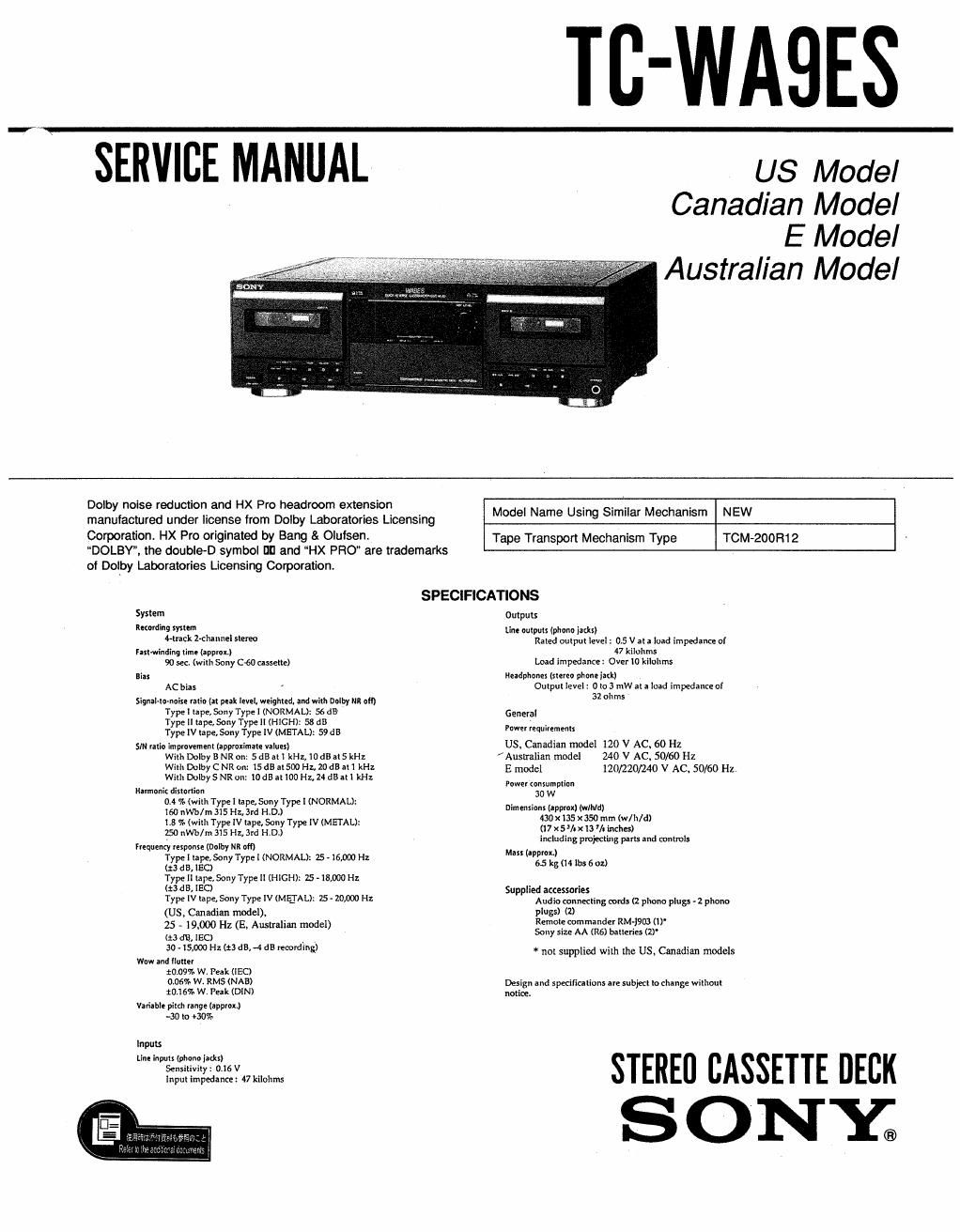
Sony tc wa 9 es service manual

This is the 51 pages manual for sony tc wa 9 es service manual.
Read or download the pdf for free. If you want to contribute, please mail your pdfs to info@audioservicemanuals.com.

Page: 1 / 51
left right
sony tc wa 9 es service manual

Extracted text from sony tc wa 9 es service manual (Ocr-read)


Page 1

TC-WAQES

SERVICE MANUAL

US Model
Canadian Model
E Model
Australian Model

Dolby noise reduction and HX Pro headroom extension
manufactured under license from Dolby Laboratories Lloensing
Corporalion. HX Pro originated by Bang & Olulsen,

DOLBY, the double-D symbol III and HX PRO are trademarks
of Dolby Laboratories Licensing Corporation.

Model Name Using Similar Mechanism NEW

TOM-200 R1 2

Tape Transport Mechanism Type

SPECIFICATIONS
Symm Outputs
"coming synem Linn outputs (plume jacks)

uracrr 2~channei stereo

ran-winding Time (zpproxJ
90 sec. (with Sony cm cassette)

aiar
AC blas ,

signaI-rmnorxe rario (or peak level, weighted, and will. 0on mr om
Type I hpe, Sony Type I (NORMAL): 56 dB
Type ll tape, Sony Type II (HIGH): 58 dd
Type Iv rape, Sony Type IV (METAL): 59 da

sm rarIo improvemenr (approxilnale vlluex)
with Dolbyl! NR on: son ati kHz,10dBal5 kHz
wmr Dolby CNR on: 15 as new Hz, 20 dB all kHz
wmr DolbySNR on: was It lDOHz. 24 dB m m:

Namenk distonion
0.4 at (with Type I tape, Sony Type I (NORMAL):
160 nWb/m 315 Ill. 37d H.D.)
Ls as (wilh Type [V rape, Sony Type IV (METAL):
$0 nWb/m 315 Hz, 3rd HAD.)
ireorrenty responxe {Dolby NR or!)
Type I rape, Sony Type I (NORMAL): 25 . 16,000 Hz
(:3 d 5, SO
Type ll \ape, Sony Type II (HlGHl: 25. 18,000 Hz
(:3 dB, IEC)
Type IV tape, Sony Type Iv (MEJAL): 75- zomo Hz
(US, Canadian model).
25 - 19,000 Hz (E, Australian model)
(£23 :13, ISO
30 - 15,000 Hz (:3 dB, -4 dB recording)
WW and "utter
20.09% W. Peak (IEC)
0.06% W. RMS (NAB)
£01655 WI Puk (DIN)

Variable pitdr range (approx)
.30 I0 430%

Inputs
Tine inorm (phone inks)
Sensitivity: 0.16 v
Input impedanee: 47 kilohms

Raled output level : 0.5 v at a Ioad impedance or
47 kilohms
Load impedance: Over Io kilollms
Headphone: (new) phone Iatt)
Output ieyeI: o to 3 rnw at a load impedance at
az ohms

General

power requirements

US. Cmadian model l20 V ACV 60 HZ
Ausualian model 240 V AC. 50/60 HZ

E model 120/220/240 V AC. 50/60 Hz

Power (onwmplion

air-tension: (approx) (will/d)
m x135 x 350 mm (w/lI/d)
(l7x5l-xlaltinchu)
including pmiecllng pan: and conrmIe
Mas! (approx)
55 k5 (I4 Ibo 602)

Supplied axessaries
Audio connecting cord: (2 phono pIrrga . z phono
plugs) (2)
Remole commander RM-l903 (0'
Sony size AA (R6) baueries (2)

* not supplied with the us. Canadian models

Deslgn and speclnulions ue subyect lo change willrour
notice.

STEREO CASSETTE DECK
S ONY®

Page 2

TABLE OF CONTENTS
§ection Iflle Ease
SECTION 1. GENERAL ...........

SECTION 2. DISASSEMBLY
2-1, Case and Front Panel
2-2. Mechanism Deck Block
2-3-1.Cassette Holder
2-3-2.0rnamenta| Plat
2~3v3.Pineh Lever, Head
2-3-4.Capstan Motor, Fly Wheel
2-3-5.Ftee| and Assist Motors ..

\lotazururAA

SECTION 3. ADJUSTMENT
3-1. Mechanism Adjustment ............................................... 8


3-2. Electrical Adjustment ......... 8
Record/Playback Head Azimuth Adjustment

9
Tape Speed Adjustment_- 9
Playback Level Adjustment-- . 10
Pitch Control Speed Adjustmen 10

Bias Current Adjustment tttttttttt
Record Bias Adjustment
Record Level Adjustment--.
Quick Reverse Sensitivity Adjustment-.
Record EQ (Type M Adjustment-- .....

SECTION 4. DIAGRAMS
4-1. Circuit Boards Location .................................................... 12
42. lC Pin Functions
' l0801 System Controller (uPD78043AGF-023-389) 13
~ l0802 Mechanism Controller (M38002M2-185FP)
. IC901 Display Contoroller (M38122M2-103FP
43. Block Diagram .......
4-4. Printed Wiring Board - Main, Panel, Deck Block -
4-5. Schematic Diagram ~ Main (1/2), Panel Block --
(Audio
4-6. Schematic Diagram - Main (2/2), Panel, Deck Block -
(System Control)
4-7. Primed Vlfirlng Board - Panel Block -
4-8, Schematic Diagram - Dolby S Block -
4-9. Printed Wiring Board ~- Dolby 5 Block - tttttttttttttttttttttttt 40

SECTlON 5. EXPLODED VIEWS
54. Case Section tttttt
52. Front Panel Sectio
5»3. Chassis Section
5-4. Mechanism Deck Section 1 (TCM-200Ft12 ..
5'5. Mechanism Deck Section 2 (TCM-200Ft12) ..................... 45

SECTION 6. ELECTRICAL PARTS LIST...
MODEL IDENTIFICATION

..46

- BACK PANEL -
3-923-1 471%
L._.| I I
US, Canadian Model : 0D (U/CA)
E Model : 1D (EZ/ES)
Australian Model : 2:! (AU)

Notes on chip component replacement

0 Never reuse a disconnected chip component.

~ Notice that the minus side of a tantalum capacitor may be
damaged by heat.

SAFETY CHECK-OUT

After correcting the original service problem, perform
the following safety checks before releasing the set to the
customer:

Check the antenna terminals, metal trim, metallized
knobs, screws, and all other exposed metal parts for AC
leakage, Check leakage as described below.

LEAKAGE

The AC leakage from any exposed metal part to earth
ground and from all exposed metal parts [0 any exposed
metal part having a return to chassis, must not exceed 0.5
mA (500 microampers). Leakage current can be measured
by any one of three methods.

1. A commercial leakage tester, such as the Simpson 229
or RCA WT-540A. Follow the manufacturers
instructions to use these instruments.

2. A battery-operated AC milliammeter. The Data
Precision 245 digital multimeter is suitable for this job.

3. Measuring the voltage drop across a resistor by means
of a VOM or battery-operated AC voltmeter. The
limit indication is 0.75 V, so analog meters must
have an accurate low-voltage scale. The Simpson 250
and Sanwa SH-63lrd are examples of a passive VOM
that is suitable. Nearly all battery operated digital
multimeters that have 3 2V AC range are suitable. (See
Fig. A)

To Exposed Metal
Parts on Set

AC
/ voltmeter
(0.75V)

0.15p.F E 1 .SKQ
'._I

i-

7 Earth Ground

Fig. A. Using an AC voltmeter to check AC leakage.

SAFETY-RELATED COMPONENT WARNING !!

COMPONENTS IDENTIFIED BY MARK A OR DOTI'ED
LINE WITH MARK A ON THE SCHEMATIC DIAGRAMS
AND IN THE PARTS LIST ARE CRITICAL TO SAFE
OPERATION. REPLACE THESE COMPONENTS WITH
SONY PARTS WHOSE PART NUMBERS APPEAR AS
SHOWN IN THIS MANUAL OR IN SUPPLEMENTS
PUBLISHED BY SONY.

ATTENTION Au COMPOSANT AYANT RAPPORT
A LA sEcuniTEi!
LES COMPOSANTS ioENTrFIE's PAR UNE MARQUE A
sun LES DIAGRAMMES SCHEMATIQUES ET LA LISTE
DES PIEcES SONT CRITIQUES POUR LA SECURITE
DE FONCTIONNEMENT. NE REMPLACER CES
COMPOSANTS OUE PAR DES PIECES SONY DONT
LES NUMEnos SONT DONNES DANs CE MANUEL ou
DANS LES SUPPLEMENTS PUBLlEs PAR SONV.

_2_