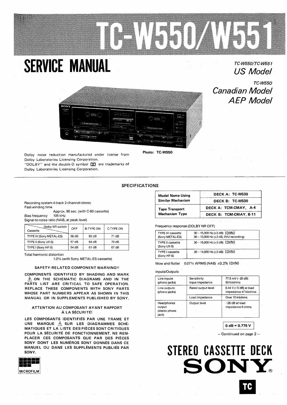
Sony tc w 550 service manual

This is the 29 pages manual for sony tc w 550 service manual.
Read or download the pdf for free. If you want to contribute, please mail your pdfs to info@audioservicemanuals.com.

Page: 1 / 29
left right
sony tc w 550 service manual

Extracted text from sony tc w 550 service manual (Ocr-read)


Page 1

SERVICE MANUAL

Dolby noise reduction manufactured under license from
Dolby Laboratories Licensing Corporation)
DOLBY and the double-D symbol D0 are trademarks of
Dolby Laboratories Licensing Corporation.

Photo: TC-W550

TC-W550/TC-W551

US Model

TC -W550

Canadian Model

AEP Model

SPECIFICATIONS

Recording system A-track 2-channel stereo
Fast-winding time

Approx. 90 sec. (with 060 cassette)
Bias frequency 105 kHz
Signal-to-noise ratio (NAB, at peak level)

Cassette by R 5mm" OFF BTVPE ON C~TYPE ON
TYPE IV (Sony METALES) 58 dB 65 as 71 dB
TYPE || (Sony uxsl 57 as 64 ca 70 dB
TYPE | (Sony HF-S) 54 dB 61 as 67 dB

Total harmonic distortion
1.0% (with Sony METAL-ES cassette)

SAFETY-RELATED COMPONENT WARNING!)

COMPONENTS IDENTIFIED BY SHADING AND MARK

A ON THE SCHEMATIC DIAGRAMS AND IN THE
PARTS LIST ARE CRITICAL T0 SAFE OPERATION.
REPLACE THESE COMPONENTS WITH SONY PARTS
WHOSE PART NUMBERS APPEAR AS SHOWN IN THIS
MANUAL OR IN SUPPLEMENTS PUBLISHED BY SONY

ATTENTION AU COMPOSANT AYANT RAPPORT
A LA SECURITEI

LES COMPOSANTS IDENTIFIES PAR UNE TRAME ET
UNE MARQUE A SUR LES DIAGRAMMES SCHE-
MATIOUES ET LA LISTE DES PIECES SONTCRITIOUES
POUR LA SECURITE DE FONCTIONNEMENT. NE REM-
PLACER CES COMPOSANTS QUE PAR DES PIECES
SONY DONT LES NUMEROS SONT DONNES DANS CE
MANUEL DU DANS LES SUPPLEMENTS PUBLIES PAR
SONY.

I
MICROFILM

Model Name Using
Similar Mechanism

DECK A: TC-W530

DECK B: TC-IN530

Tape Transport
Mechanism Type

DECK A: TCM-CMAY, A-4

DECK B: TCM-CMAY, B-11

Frequency response (DOLBY NR OFF)

TYPE IV cassette

30,15,00on(=3¢5) (DIN)

(stereo phone

jack)

(Sony METALES) 30 -- 13,000 HZ (:3 dB, DVU recordlng)
TYPEIlcassette all-15,000 H2(:3 dB) (DIN)
(Sony uxsl
1'va | cassette 30 - 14,000 HZ (:3 dB) (DI N)
(Sony HF-S)
Wow and flutter 007% WRMS (NAB) $0.296 IDINI
lnpuls/Outpuls
Line inputs Sensitivlly 77.5 mV (-20 dB)
(phono iacks) Input impedance 50 kilohms
Line outputs Rated output level 0.44 v (-5 as) at load
(phone lacks) impedance 47 kilonms
Load impedance Over 10 kilohms
Headphones Output level A23 dB at load
output impedance 8 ohms

- Continued on page 2 -

STEREO CASSETTE DECK
SONY;

TC

Page 2

TC-WSSO/WSS'I

General
Power requirements
US, Canadian model:
120 v Ac, so Hz
AEP model:
220 V AC, 50/60 Hz
Approx. 430 x 130 x 275 mm (wlh/d)
(17 x 51/; X107/3 inches)
including projecting parts and controls
Weight Approx, 4.9 kg (10 lbs 13 oz]
Supplied accessories
Connecting cord (2)
Remote control cord (1)
Optional accessory '
Wireless remote control unit RM-88

Dimensions

W

SECTION 1
1-1.

1-2.

1-3.
SECTION 2
SECTION 3

3-1.

3-2.
SECTION 4
SECTION 5

5-1.

FEATUR

Double decks
The unit consists of two decks: deck A for playback and deck
B for recording/playback.

Twospeed dubbing
Normal speed for dubbing while monitoring the selections.
High speed for dubbing the whole cassette in a short time,

Edit tunctions

By pausing the decks manually while dubbing, you can
search for any portion to be dubbed with the
rightward/leftward fast winding.

Type B and c Dolby noise reduction * system
Reduces tape hiss noise in low level high frequency signals.

Other features

0 Relay playback for long hours

- Synchronized recording with a turntable system (for TC-
W551 )

0 Record muting

0 Handy remote control operation (with the optional Sony
RM68 remote control unit) '

' Dolby noise reduction manutactuved under license 1mm Dolby Laboratories
Licensing Corporation.
"DOLBV" and the doubleD D0 are trademarks of Dolby Laboratories
Licensing Comomtion.

5-2.
SECTION 6

SECTION 7
SECTION 8

Tible of Contens

the Page
OUTLINE ................. 3
LOCATION AND FUNCTION OF
CONTROLS .............. 3
IC501 (M50742-404) PIN
FUNCTIONS .............. 6
BLOCK DIAGRAM .......... 9
DISASSEMBLY ............. 11
ADJUSTMENTS ............ 13
MECHANICAL ADJUSTMENTS . I3
ELECTRICAL ADJUSTMENTS . . l4
CIRCUIT BOARDS LOCATION . l8
DIAGRAMS ............... 19
MOUNTING DIAGRAM ....... l9
SCHEMATIC DIAGRAM ...... 23
EXPLODED VIEWS AND

PARTS LISTS ............. 29
ELECTRICAL PARTS LIST . . . . 34
TROUBLESHOOTING ........ 4 l