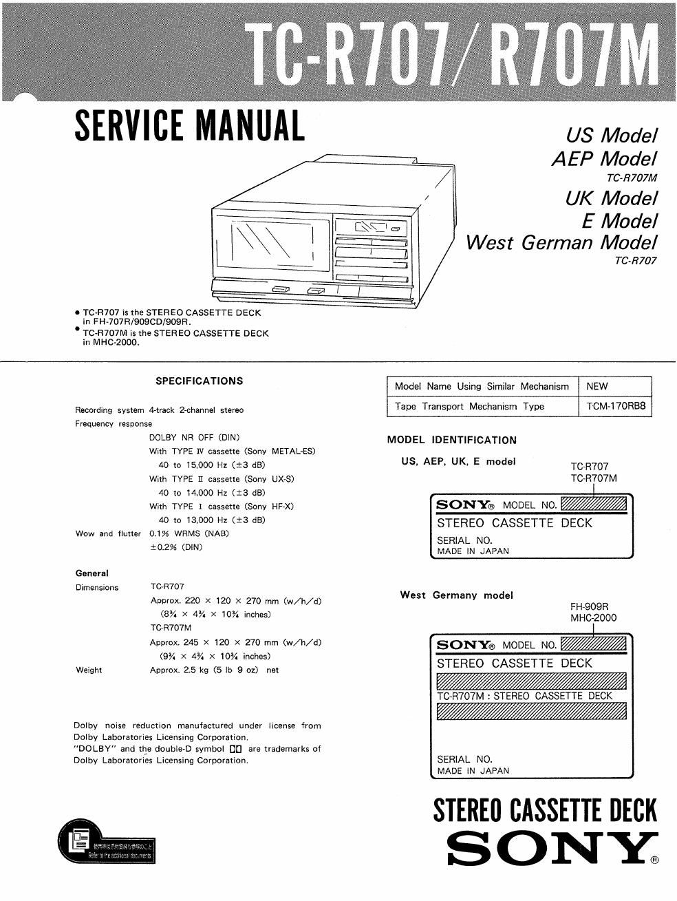
Sony tc r 707 m service manual

This is the 21 pages manual for sony tc r 707 m service manual.
Read or download the pdf for free. If you want to contribute, please mail your pdfs to info@audioservicemanuals.com.

Page: 1 / 21
left right
sony tc r 707 m service manual

Extracted text from sony tc r 707 m service manual (Ocr-read)


Page 1

US Model
AEP Model

/ TC-R707M

/ UK Model

U TC-R707 is the STEREO CASSETTE DECK
in FH-707R/90900/909R.

. TC-R707M is the STER E0 CASSETTE DECK
in MHC-ZOOOr

E Model
West German Model

TC-R707

SPECIFICATIONS

Recording system 4»track 2-channel stereo
Frequency response
DOLBY NR OFF (DIN)
With TYPE IV cassette (Sony METAL-ES)
40 to 15,000 Hz (t3 dB)
With TYPE I] cassette (Sony UXS)
40 to 14.000 Hz (:3 dB)
With TYPE I cassette (Sony HF-X)
40 to 13,000 Hz (i3 dB)
Wow and flutter 01% WRMS (NAB)

10.2% (DIN)
General
Dimensions TGR707
Approx 220 X 120 X 270 mm (w/h/d)
(8% x 4% x 10% inches)
TCR707M
Approx. 245 X 120 X 270 mm (w/h/d)
(9% X 4% x 10% inches)
Weight Approx 25 kg (5 lb 9 oz) net

Dolby noise reduction manufactured under license from
Dolby Laboratories Licensing Corporation.
DO LBY" and tile double-D symbol D0 are trademarks of
Dolby Laboratories Licensing Corporation.

Model Name Using Similar Mechanism NEW

Tape Transport Mechanism Type TCM-l7ORB8

MODEL IDENTIFICATION

US, AEP, UK, E model TC~R707

TC-R707M

SONY!) MODEL NO. W
STEREO CASSETTE DECK

SERIAL NO.
MADE IN JAPAN

West Germany model
FH-909R
MHC-2000

SONY® MODEL NO. W
STEREO CASSETTE DECK

WWW

TCvR707M : STEREO CASSETTE DECK

WWW

SERIAL NO.
MADE IN JAPAN

STEREI] CASSETTE DECK

SONXC

Page 2

TC-R707/R707M

REPAIRING PRECAUTION

[To apply B+ voltage]

The power of this unit is fed from amplifier.
Because of ihis. connect the regulated power supply
as illustrated below when this unit alone operates.

regulated dc power supply

regulated dc power supply

(1.5-2.0A) (1.5-20A)
mml-HZV +l8Vlmm
+ I. I .° +
GND 0'- -°| GND

-12V

-
-( LINE IN (RI)-

connector

board

audio svscon

NOTE ON REPLACEMENT OF MECHANISM
CHASSIS ASSEMBLY

The mechanism chassis assembly is supplied as shown
below with the bosses @ to G) on service.
On replacement please finish as shown in the figure.

Cut the bosses @ 0 (D with such as
culling plier.

mechanical chassis assv
(X-83434181)