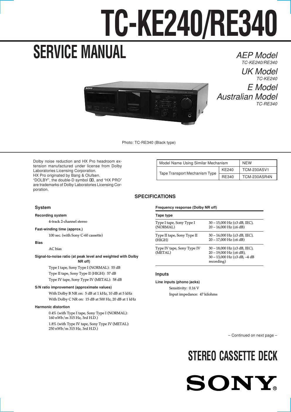
Sony tc ke 240 service manual

This is the 40 pages manual for sony tc ke 240 service manual.
Read or download the pdf for free. If you want to contribute, please mail your pdfs to info@audioservicemanuals.com.

Page: 1 / 40
left right
sony tc ke 240 service manual

Extracted text from sony tc ke 240 service manual (Ocr-read)


Page 1

2 SAFETY-RELATED COMPONENT WARNING!! COMPONENTS IDENTIFIED BY MARK 0 OR DOTTED LINE WITH MARK 0 ON THE SCHEMATIC DIAGRAMS AND IN THE PARTS LIST ARE CRITICAL TO SAFE OPERATION. REPLACE THESE COMPONENTS WITH SONY PARTS WHOSE PART NUMBERS APPEAR AS SHOWN IN THIS MANUAL OR IN SUPPLEMENTS PUB- LISHED BY SONY. Notes on chip component replacement ¥ Never reuse a disconnected chip component. ¥ Notice that the minus side of a tantalum capacitor may be dam- aged by heat. Outputs Line outputs (phono jacks) Rated output level: 0.5 V at a load impedance of 47 kilohms Load impedance: Over 10 kilohms Headphones (stereo phone jack) Output level: 0.25 mW at a load impedance of 32 ohms General Power requirements Europe and certain countries in Asia: 220 Ð 230 V AC, 50/ 60 Hz Australia: 240 V AC, 50/60 Hz Other countries: 110 Ð 120/220 Ð 240 V AC, 50/60 Hz Power consumption TC-RE340: 15 W TC-KE240: 14 W Dimensions (approx.) (w/h/d) 430 ´ 120 ´ 290 mm Mass (approx.) 3.3 kg Supplied accessories Audio connecting cords (2) Design and specifications are subject to change without notice.

Page 2

3 SECTION 1 SERVICING NOTE TABLE OF CONTENTS 1. SERVICING NOTE .................................................. 3 2. GENERAL ................................................................... 4 3. DISASSEMBLY ......................................................... 5 4. MECHANICAL ADJUSTMENTS ....................... 10 5. SERVICE MODE ...................................................... 11 6. ELECTRICAL ADJUSTMENTS ......................... 12 7. DIAGRAMS 7-1. Note for Printed Wiring Boards and Schematic Diagrams ....................................................... 15 7-2. Printed Wiring Boards Ð HEAD RELAY (REC/PB)/ LEAF SW (REC/PB) Boards Ð ....................................... 18 7-3. Printed Wiring Board Ð MAIN Board Ð ........................ 19 7-4. Schematic Diagram Ð MAIN Section (1/2) Ð ................ 20 7-5. Schematic Diagram Ð MAIN Section (2/2) Ð ................ 21 7-6. Printed Wiring Boards Ð TRANS/POWER SW Boards Ð ................................... 22 7-7. Schematic Diagram Ð TRANS/POWER SW Boards Ð ................................... 23 7-8. Printed Wiring Board Ð DISPLAY Board Ð .................. 24 7-9. Schematic Diagram Ð DISPLAY Board Ð ..................... 25 7-10. Printed Wiring Boards Ð KEY/HP Boards Ð ................. 26 7-11. Schematic Diagram Ð KEY Board Ð ............................. 26 7-12. IC Pin Function Description ........................................... 28 8. EXPLODED VIEWS ................................................ 30 9. ELECTRICAL PARTS LIST ............................... 33MODEL IDENTIFICATION Ð BACK PANEL Ð Part No. Model Part No. TC-KE240AEP model 3-042-502-0s UK model 3-042-502-1s AEP model 3-042-490-0s TC-RE340 Australian model 3-042-490-1s Singapore model 3-042-490-2s