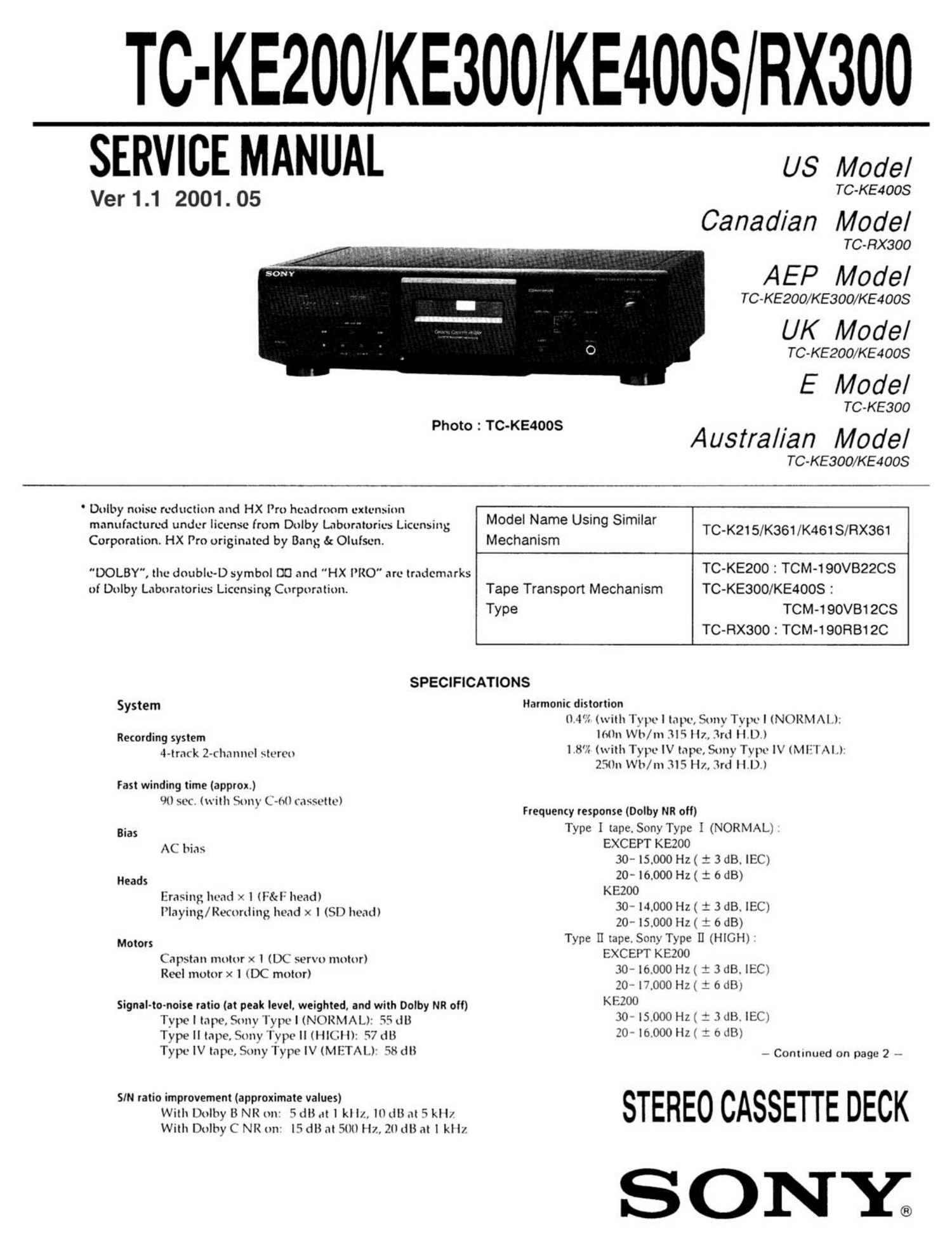
Sony tc ke 200 service manual

This is the 34 pages manual for sony tc ke 200 service manual.
Read or download the pdf for free. If you want to contribute, please mail your pdfs to info@audioservicemanuals.com.

Page: 1 / 34
left right
sony tc ke 200 service manual

Extracted text from sony tc ke 200 service manual (Ocr-read)


Page 1

TC-KE200 KE300 KE4OOS RX300

SERVICE MANUAL us Model

Ver1.1 2001.05 . TC-KE4008
Canad/an Model

TC -RX300

AEP Model

TC -KE200/KE300/KE4008

UK Model

TC-KE200/KE4OOS

E Model

TC-KE300

Ph t :TC-KE4OOS .
°° Austral/an Model
TC-KE300/KE4OOS

' Dolby noise reduction and HX Iro headroom extemion . .
manufactured under license from Dolby Laboratories Licensing Medal Name US'ng S'm'lar

TC-K215 K 1 K4 1 RX 1
Corporation. HX Pro originated by Bang&0lufsen. Mechanism / 36 I 6 8/ 36

"DOLBY", the double-D symbol DO and HX lRO" are trademarks TC'KE200 : TCM'190V822CS
ot Dolby Laboratories Licensing Corporation. Tape Transport Mechanism TC-KE300/KE4OOS :

Type TOM-190V812CS
TC-RX300 : TOM-190R812C

SPECIFICATIONS

System Harmonic distortion

(H'fi (with Type I tape, Sony Type I (NORM/\l .l.
lolln Wh/m 3F» 2, 3rd II.I,),l

lill'll (with Type IV tape, Sony Type IV (Mll AI.)-
25(ln Wh/m RIS Hz, 3rd |I.I,).)

Recording system
4-track 2-Channel stereo

Fast winding time (approx)

()(lsec.(withSonyC-otleaxsettel F (D lb NR ll)
requency response 0 y 0

Type I tape. Sony Type I (NORMAL)
EXCEPT KEZOO
30~ [5.000 Hz( i 3 dB. IEC)
20- l6.000 Hz( : 6 dB)
KEZOO
30 H.000 Hz( : 3 dB. lEC)
20- l5,000 Hz( : 6 dB)
Type II tape. SonyType 1] (HIGH) '
EXCEPT KEZOO
30- I6.000 HZ( i 3 dB, IEC)
30 - H.000 H2( 1 0 dB)

Bias
AC bias

Heads
Erasing head .V. l (l:&l" head)
Playing/Recording head x l (SI) head)

Motors
Capstan motor x 1 (DC servo motor)
Reel motor x I (DC motor)

Signal-to-noise ratio (at peak level, weighted. and with Dolby NR oft) KEZOU _ \
Type I tape, Sony 'I'ype I (NORMAL): 55 LIB 30' -000 HZI : 3 lB- 39)
Type II tape, Sony I'ype II (I (II It: 57 dB 3 ' '0000 U I 0 RIB)
Type IV tape, Sony Type IV (METAL): '48 (Ill _ Continued on page 2 e

SIN ratio improvement (approximate values)
With Dolby B NR on- 5 dB at l kl It, 10 (IB at 5 kl I/
With Dolby C NR on 15 dB at 500 Hz, 20 dB at l kl Iz

Page 2

Type IV tape. Sony Type IV (METAL) :

EXCEPT KEZOO
30-18000 Hz ( i 3 dB. lEC)
30- 13,000 Hz ( i 3 dB. - 4 dB recording)
20-19000 Hz( : 6 dB)

KE200
30-15000 Hz ( i 3 dB. lEC)
30-11000 Hz( i 3 dB, - 4 dB recording)
20- l6.000 Hz( : 6 dB)

Wow and flutter
: 0.13% W. Peak (lEC)
0.07% W. RMS (NAB)
10.18% W. Peak (DIN)

Inputs

Line inputs (phono jacks)
Sensitivity: 0.16 V
Input impedance: 47 kilohms

Outputs

Line outputs (phono jacks)
Rated output level: 0.5 V at a load impedance of
47 kilohms
Load impedance: Over 10 kilohms

Headphones (stereo phone jack)

Output level: 0.25 mW at a load impedance of
32 ohms

General

Power requirements

M

Where purchased Power requirements

US. Canadian model . l20 V AC. 60 Hz

AEP, UK. German.

Malaysia. Singapore model : 220 - 230 V AC_ 50/60 Hz

Australian model : 240 V AC. 50/60 Hz

Emodel: HO- 120V or 220- 240VAC,50/60 Hz

adjustable with the voltage selector

Power consumption
l9 W (EXCEPT KEAOOS)

20 w (KE4OOS)

Dimensions (approx) (wlhld)
430x120x 3) mm ()7 x 4 /r x l2 '/i inches)
incl. projecting parts and controls

Mass (approx)
3.5 kg (7 lbs ll 07.)

Supplied accessories
Audio connecting Cords (2)

Design and specifications are subject to change without
notice.

TABLE OF CONTENTS

Specifications ............................................................... l
1. GENERAL
Identifying the Parts on the Front Panel -------------------------- 4

. DISASSEMBLY

2.1. Front Panel Removal ........................................... 5
2-2. Mechanism Deck Section Removal -------------------------- 5
2-3. Head and Pinch Roller Removal ---------------------------- 6
2_4_ Fitting Base Block Removal .................................. 6
2-5. Motor Removal .................................................. 6

. ADJUSTMENTS

3-1_ Mechanical Adjustments ....................................... 7
3-2. Electrical Adjustments ......................................... 7
. EXPLANATION OF IC TERMINALS ----------------------- 10
. DIAGRAMS
5-1. Printed Wiring Boards - Main Section -
(TC-KEZOO/KE300/RX300) ................................ 12
5-2. Schematic Diagram - Main Section -
(TC-KEZOO/KE300/RX300) ................................ 1 5
5-3. Schematic Diagram - Main Section --
(TC-KE40()S) .................................................. 20
5-4. Printed Wiring Boards - Main Section -
(TC.KE400$) .................................................. 25
5.5_ Circuit Boards Location ...................................... 28
5-6. Printed Wiring Boards - Audio Section - ------------- 29
5-7. Schematic Diagram - Audio Section - ---------------- 33

. EXPLODED VIEWS

6-1 _ Chassis Section ................................................ 37
6-2. Front Panel Section ........................................... 39
6.3_ Mechanism Section I ......................................... 40
6-4. Mechanism Section 2 ......................................... 41
' ELECTRICAL PARTS LIST ................................... 42