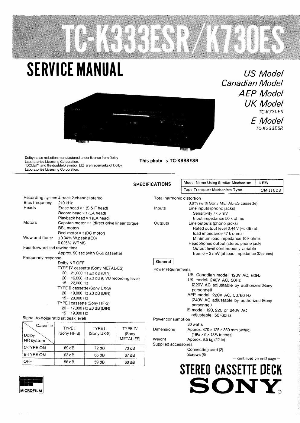
Sony tc k 333 esr service manual

This is the 36 pages manual for sony tc k 333 esr service manual.
Read or download the pdf for free. If you want to contribute, please mail your pdfs to info@audioservicemanuals.com.

Page: 1 / 36
left right
sony tc k 333 esr service manual

Extracted text from sony tc k 333 esr service manual (Ocr-read)


Page 2

TC-K333ESR/K730ES

OPERATING VOLTAGE

Display range -40 to +8 dB
Frequency response
20 - 20,000 Hz 21.5 dB
Attack time 1 ms
Recovery time 750 ms (from 0 to -20 dB)
Number of display segments
16each tor left and right channel

Before connecting the unit to the power source, check that
the operating voltage of your unit is the same as the local
power line voltage

The USA and Canada model operates on 120 V AC.

The European model operates on 220 V AC (or 240 V AC
adjustable by authorized Sony personnel).

The United Kingdom model operates on 240 V AC (or 220 V
AC adiustable by authorized Sony personnel).

The model for other countries operates on 120, 220 or 240 V
AC. The voltage selector is located on the rear panel. It the
selector must be reset, disconnect the AC power cord
and set the selector to the appropriate voltage.

Design and specifications are subject to change without notice
Note

This appliance conforms with EEC Directives 76/889 and 82/499
regarding interierence suppression.

TABLE OF CONTENTS

Section Title Page
- MODEL IDENTIFICATION
-- Specification Label -
1. GENERAL
lvlr Location and Function of Controls ................ 3
TC-K333ESR, TC-K730ES
2. MECHANICAL ADJUSTMENTS .................. 4
3. ELECTRICAL ADJUSTMENTS .................... 7 SOIVIYO MODEL Nor m
STEREO CASSETTE DECK
4. DIAGRAMS
4-1. Semiconductor Lead Layouts ...................... 16 1
4-2. Printed Wiring Board *Audio Section- . .17
4-3. Schematic Diagram -Audio Section- ............ 21

4-4.
4-5.

Printed Wiring Board ~System Control Sectioni 4 .25

Schematic Diagram -System Control Section- ....29 SER'AL N0-

MADE IN JAPAN

5. EXPLODED VIEWS

5-1. Case ............................................ 33 AEP M d | AC 220V 50/60H
0 e I I ~ Z
- ...................................... 34
5 2 From,Panel 35 UK Model: AC: 240 V~50/60 Hz
5-3. Chass1s .......................................... E Model: AC: 120/220/240 V~50/60 Hz 30 W
5"" MeChanism seam (1) """""""""""""" 36 us Model: AC: 120 v 60 Hz 30 w
5-5. Mechanism Section (2) ..................... ..38 Canadian Model: AC: 120 V 60 Hz 30 W
6. ELECTRICAL PARTS LIST ...................... 40

SAFETY-RELATED COMPONENT WARNING
COMPONENTS IDENTIFIED BY SHADING AND MARK

ATTENTION AU COMPOSANT AYANT RAPPORT
A LA SECURITE!

A ON THE SCHEMATIC DIAGRAMS AND IN THE
PARTS LIST ARE CRITICAL TO SAFE OPERATION.
REPLACE THESE COMPONENTS WITH SONY PARTS
WHOSE PART NUMBERS APPEAR AS SHOWN IN THIS
MANUAL OR IN SUPPLEMENTS PUBLISHED BY SONY.

LES COMPOSANTS IDENTIFIES PAR UNE TRAME ET
UNE MAROUE A SUR LES DIAGRAMMES SCHE-
MATIOUES ET LA LISTE DES PIECES SONTCRITIOUES
POUR LA SECURITE DE FONCTIONNEMENT. NE FIEM-
PLACER CES COMPOSANTS QUE PAR DES PIECES
SONY DONT LES NUMEROS SONT DONNES DANS CE
MANUEL 0U DANS LES SUPPLEMENTS PUBLIES PAR
SONY.