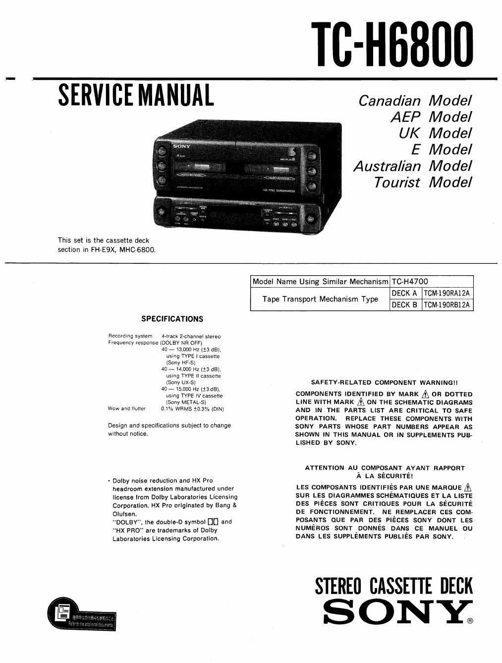
Sony tc h 6800 service manual

This is the 38 pages manual for sony tc h 6800 service manual.
Read or download the pdf for free. If you want to contribute, please mail your pdfs to info@audioservicemanuals.com.

Page: 1 / 38
left right
sony tc h 6800 service manual

Extracted text from sony tc h 6800 service manual (Ocr-read)


Page 1

SERVICE MANUAL

This set is the cassette deck
section in FH-E9X, MHC-6800

TC-HBBUII

Canadian Model
AEP Model

UK Model

E Model
Australian Model
Tourist Model

SPECIFICATIONS

Recording system rack Zvchannel stereo
Frequency response IDOLBY NR OFF)
40 -13,000 H1123 (13).
using TYPE 1 cassette
(Sony HRS)
40 -14000 HZ (13 dBI.
usmg TYPE || cassette
(Sony um;
40 ~15.000 H1123 d8),
usmg TYPE IV cassette
(Sony METAL-S)
Wow and IIutler 0.1% WRMS t0 3% (DIN)

Design and specifications subject to change
without notice

- Dolby noise reduciion and HX Pro
headroom extension manufactured under
license lrorn Dolby Laboratories Licensing
Corporation HX Pro originated by Bang &
OluIsent
DOLBY. the double-D symbol DD and
HX PRO" are trademarks of Dolby
Laboratories Licensing Corporation

Model Name Using Similar Mechanism TC-H4700

Tape Transport Mechanism Type

DECK A TOM-190RA12A
DECK B TCM-lQORBlZA

SAFETYARELATED COMPONENT WARNINGI!

COMPONENTS IDENTIFIED BY MARK A 0R DOTTED
LINE WITH MARK A ON THE SCHEMATIC DIAGRAMS
AND IN THE PARTS LIST ARE CRITICAL TO SAFE
OPERATION. REPLACE THESE COMPONENTS WITH
SONY PARTS WHOSE PART NUMBERS APPEAR AS
SHOWN IN THIS MANUAL OR IN SUPPLEMENTS PUB-
LISHED BV SONY.

ATTENTION AU COMPOSANT AYANT RAPPORT
A LA SECURITEI

LES composmrs IDENTIFIES PAR UNE MARQUE @
sun LES DIAGRAMMES SCHEMATIOUES ET LA LISTE
DES PIECES sonr CRITIQUES POUR LA sécunrré
DE FONCTIONNEMENT. NE REMPLACER ces COM-
POSANTS oUE PAR DES PIECES SONY DONT LES
NUMéRos som' DONNés DANS CE MANUEL ou
DANS LES SUPPLEMENTS Pusués PAR SONY.

STEREu CASSETTE DECK
S 0 NE

Page 2

NOTE FOR REPAIRING

Usually, the power amplifier TA-H6800N is connected to this
set to supply the power to it

When repairing this set alone, as shown below, short TP601
on the TC main board, then connect 18Vac to pins ® and ®
of CNJ 401 on the connector board.

" Shim

ITC MAIN BOARDI (CONDUCTOR SIDE)

CONNECTOR cuuoi ACIBV
/

CNJ40I

[CONNECTOR BOARD] (CONDUCTOR SIDE)

MODEL IDENTIFICATION
-BACK PANEL-

G)
:1 e9
SYSTEM CONTROL AU BUS 'Abbrsviations
|T : Italian model
EA : Saudi Arabia model
AUS: Australian model
JE : Tourist model
MY : Malaysia model
SP : Singapore model

3-382505-21 AE -. AEP, UK, IT, 3 EA, Aus, JE MY. sp model
m// 338260531 AE4: German model
3-382-505-81 CA : Canadian model

_2_