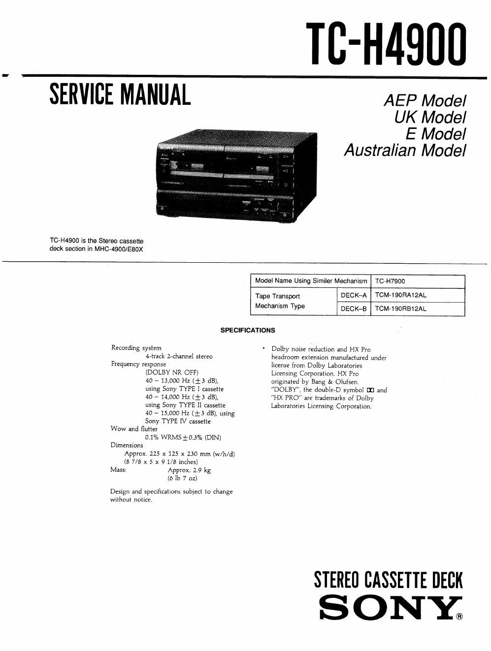
Sony tc h 4900 service manual

This is the 32 pages manual for sony tc h 4900 service manual.
Read or download the pdf for free. If you want to contribute, please mail your pdfs to info@audioservicemanuals.com.

Page: 1 / 32
left right
sony tc h 4900 service manual

Extracted text from sony tc h 4900 service manual (Ocr-read)


Page 1

TB-H4900

SEIiVICE MANUA'L AEP Mode,

UK Model
E Model
Austral/an Model

TCeH4900 is the Stereo cassette
deck section in MHC-ASOO/ESOX

Model Name Using Simiier Mechanism TC-H7900

Tape Transpon DECK-A TOM-190RA12AL
Mechanism Type DECK-B TCM-190RB12AL
SPECIFICATIONS
Recording system ' Dolby noise reduction and HX Pro
4-track Lchannel stereo headroom extension manufactured under
Frequency response license from Dolby Laboratories
(DOLBY NR OFF) Licensing Corporation. HX Pro
40 - 13,000 Hz (i3 dB), originated by Bang 5: Olufsen.
using Sony TYPE I cassette DOLBY, the double-D symbol II] and
40 - 14,000 Hz (i3 dB), HX PRO are trademarks of Dolby
using Sony TYPE Ii cassette Laboratories Licensing Corporation.

40 - 15,000 Hz (is dB), using
Sony TYPE IV cassette
Wow and flutter
0.1% WRMSi-O,3% (DIN)
Dimensions
Approx. 225 x 125 x 230 mm (w/h/d)
(8 7/8 x 5 x 91/8 incliES)
Mass: Approx. 2.9 kg
(6 lb 7 oz)

Design and specifications subject to change
without notice.

STEREO CASSETTE DECK
S ONY;

Page 2

SERVICE NOTE

. Power Supply Used in Servicing
This unit does not have its own power supply. As it works on the
power supplied from the amplifier (TA-H4900) and equalizer
(SEQ-H4900) used for this series, connect this amplifier when
servicing the unit (conduction repair, etc.)

Notes on chip component replacement

0 Never reuse a disconnected chip component.

- Notice that the minus side of a tantalum capacitor may be
damaged by heat.

TABLE OF CONTENTS
§e§1ign Illa Base

1 . GENERAL ............................................................... 3

2. DISASSEMBLY
Front Panel Assembly .
SW (A), (B) Board .......
MD Block ...........
Cassette Retainer
Mechanism Deck .
Head Base Assembly ..
Capstan/Reel Motor .....


uIOIUiJsJaAA

3. MECHANICAL ADJUSTMENTS 6
4. ELECTRICAL ADJUSTMENTS ............................. 6
5. DIAGRAMS

5-1t Circuit Boards Location .......
5-2. Semiwnductor Lead Layouts .
5-3. Block Diagram .........................................
5-4. Printed Wiring Boards - Main Section -
5-5t Schematic Diagram - Main Section - ..
5-6. Schematic Dimram - Panel/Power Section
5-7. Printed Wiring Boards -- Panel/Power Section -
5-8. IC Pin Functions

' [C301 FL Driver (M38122-M2-060FP) t

- |0601 System Control (uPC78052-020) t


6. EXPLODED VIEWS
6-1. Case and Chassis Section
6-2. Cassette Holder Section ..
6»3. Mechanism Deck Section-1
(DECK A: TCM-190RA12AL/DECK B: TCM-190RB12AL)
.............................................. 34
6-4. Mechanism Deck Section-2
(DECK A: TOM-190RA12AL/DECK B: TCM»19OFIB12AL)
............................................................................................ 35

7. ELECTRICAL PAFITS LIST ...................................... 36

SAFETY-RELATED COMPONENT WARNING I!

COMPONENTS IDENTIFIED BY MARK A OR DOTTED

LINE WITH MARK A ON THE SCHEMATIC DIAGRAMS
AND IN THE PARTS LIST ARE CRITICAL TO SAFE

OPERATION. REPLACE THESE COMPONENTS WITH
SONY PARTS WHOSE PART NUMBERS APPEAR AS
SHOWN IN THIS MANUAL OR IN SUPPLEMENTS

PUBLISHED BY SONY.