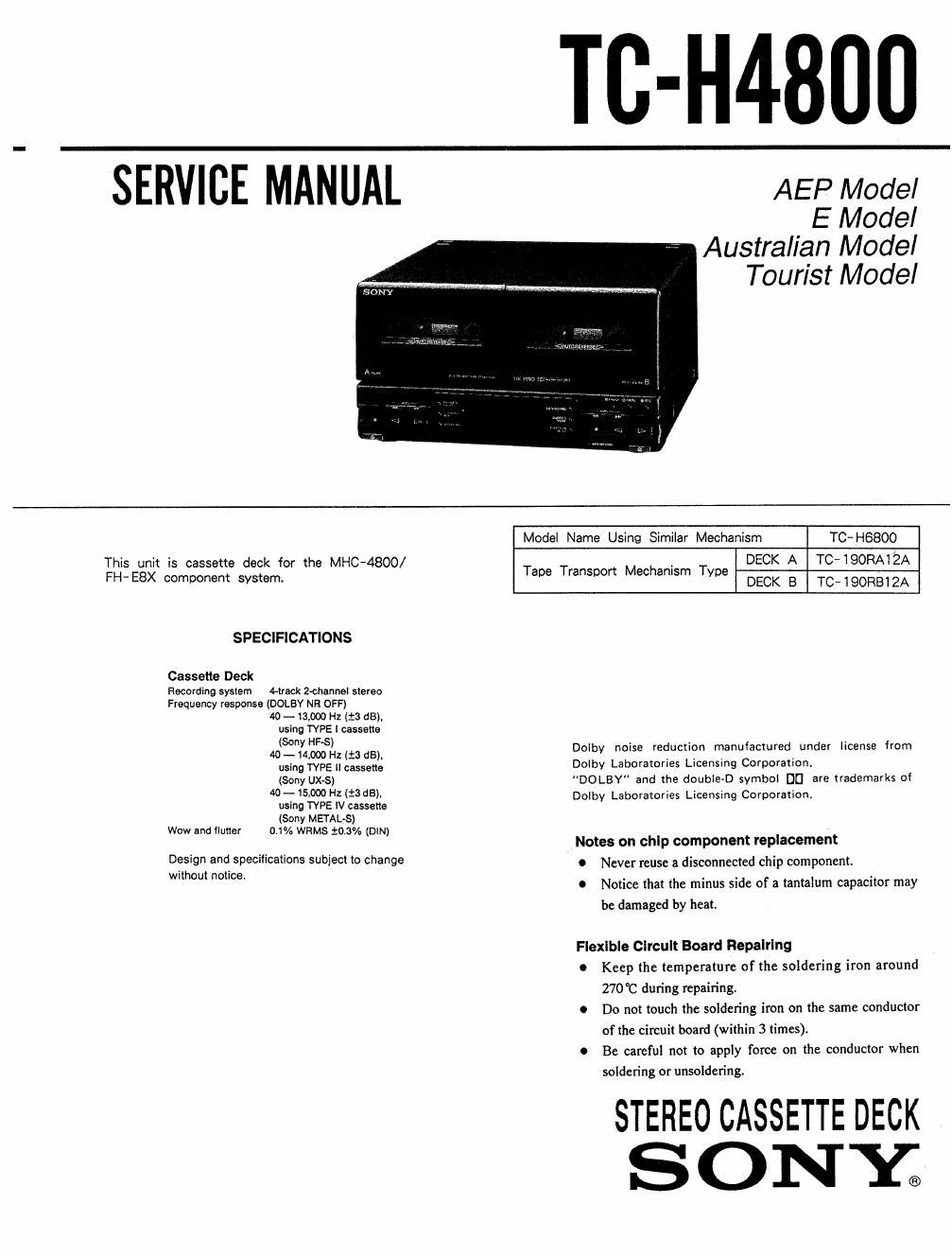
Sony tc h 4800 service manual

This is the 28 pages manual for sony tc h 4800 service manual.
Read or download the pdf for free. If you want to contribute, please mail your pdfs to info@audioservicemanuals.com.

Page: 1 / 28
left right
sony tc h 4800 service manual

Extracted text from sony tc h 4800 service manual (Ocr-read)


Page 1

TC-H4800

SERVICE MANUAL AEP Model

E Model
Australian Model
Tourist Model

Model Name Using Similar Mechanism TC-HBBOO
This unit is cassette deck for the MHC-4800/ . DECK A TCJQORAQA
FH»E8X component system. Tape mm Mmhan'sm Type DECK a TC-TQORBTZA

SPECIFICATIONS

Cassette Deck
Recording system rack 2-channel stereo
Frequency response (DOLBY NE OFF)
M) -13.000 Hz (£3 68),
using TYPE l cassette

Sc HES . .
40(-n1):1.000l)'lz(.t365), Dolby noise reduction manufactured under license from

using TVPE ll cassette Dolby Laboratories Licensing Corporation.

(30W UXS) DOLBY and the double-D symbol DC] are trademarks of

40 - 15.000 Hz (13 63).
using TYPE IV cassette
(Sony METAL-S)
Wow and flutter 0.1% WRMS 20.3% (DlN)

Dolby Laboratories Licensing Corporation,

Notes on chip component replacement

0 Never reuse a disconnected chip component.

0 Notice that the minus side of a tantalum capacitor may
be damaged by heat.

Design and specifications subject to change
without notice.

Flexible Clrcult Board Repalrlng

0 Keep the temperature of the soldering iron around
270°C during repairing.

0 Do not touch the soldering iron on the same conductor
of the circuit board (within 3 times).

0 Be careful not to apply force on the conductor when
soldering or unsoldering.

STEREO CASSETTE DECK

SONY;

Page 2

TABLE OF CONTENTS

Section Title Page
1. GENERAL ~

2, DISASSEMBLY ........ . .............................. 4
a. MECHANICAL ADJUSTMENTS ....................... 3
4. ELECTRICAL ADJUSTMENTS ........................ 6
5. DIAGRAMS

5-1. Semiconductor Read Layouts ------------------ 10
5-2. Circiut Boards Location ~

5-3. Printed Wiring Boards ......................... 11
5-4. Schematic Diagram --Main Section- --------- 15
5-5. Schematic Diagram Panel Section- ~~~~~~~ 20
5-6. Block Diagram ................................. 23

5-7. IC Block Diagram ~~~~~~~~~~~~ ~ 25

CAUTION WHEN REPAIRING

This unit is connected to power amplifier TA-H4800, which
supplies normally the power to this unit. However, when
repairing this unit only, connecter board after shorting the
T P601 on the main board as shown in the following

diagrams :

short

E
ACl 8V

Section Title Page

6. EXPRODED VIEWS

6- 1. Front Panel Section - l ------------------- 27
6-2. Front Panel Section-Z ~~~~~~~~~~~~~~~~~~~~~~ 28
6-3. Mechanism Section - l ~~~~~~~~~~~~~~~~~~~~~~~~~ 29
6-4. Mechanism Section - 2 ------------------------ so
7. ELECTRICAL PARTS LIST ~~~~~~~~~~~~~~~~~~~~~~~~~ 31

SAFETY-RELATED COMPONENT WARNING

COMPONENTS IDENTIFIED BV MARK A on DOTTED
LINE WITH MARK A ON THE SCHEMATIC DIAGRAMS
AND IN THE PARTS LIST ARE CRITICAL To SAFE
OPERATION. REPLACE THESE COMPONENTS WITH
soNv PARTS WHOSE PART NUMBERS APPEAR As
SHOWN IN THIS MANUAL on IN SUPPLEMENTS PUB-
LISHED BY SONY.

[TC MAIN BOARD} (SOLDERED SIDE)

' IPsoI
um

[CONNECTOR BOARD) (SOLDERED SIDE)