Sony TC EX100 Service Manual

This is the 27 pages manual for Sony TC EX100 Service Manual.
Read or download the pdf for free. If you want to contribute, please mail your pdfs to info@audioservicemanuals.com.

Page: 1 / 27
left right
Sony TC EX100 Service Manual

Extracted text from Sony TC EX100 Service Manual (Ocr-read)


Page 1

TC-EXBfl/EXI'UU

SERVICE MANUAL

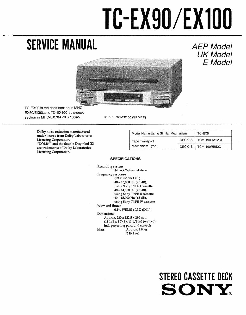
TC-EX90 is the deck section in MHC-
EX50/EX90, and TC-EX1 00 isthe deck
section in MHC-EX70AV/EX1OOAV.

AEP Model

Photo :TC-EXIOO (SILVER)

UK Model
E Model

Dolby noise reduction manufactured
under license from Dolby Laboratories
Licensing Corporation.

DOLBY and the double-D symbol 1:]
are trademarks of Dolby Laboratories
Liceming Corporation.

Model Name Using Similar Mechanism

TC-EX5

Tape Transport DECK-A

TOM-190RA1ZCL

Mechanism Type DECK-B

TCM-190RB52C

SPECIFICATIONS

Recording system
4-track 2-channel stereo
Frequency response
(DOLBY NR OFF)
40 - 13,000 Hz (:3 dB),
using Sony TYPE I cassette
40 - 14,000 Hz (13 dB),
using'Sony TYPE ll cassette
4U -- 15,000 Hz (:3 dB),
using Sony TYPE IV cassette
Wow and flutter
0.1% WRMS 10.3% (DIN)
Dimensions
Approx. 280 x 122.5 x 280 mm
(11 1/8 x 4 7/8 x 11 1/8 in) (w/h/d)
incl. projecting parts and controls
Mass Approx. 2.8 kg
(6 lb 2 oz)

STEREO CASSETTE DECK
S 0 NY;

Page 2

MODEL IDENTIFICATION
-- BACK PANEL -

[

TC-EX100 (AEP, UK Model) : 4-978-260-0El
TC-EX100 (E Model) : 4-978-2604 El
TC-EX100 (Saudi Arabia Model) : 4-978~260-2D

TC-EX100 (Thailand Model) : 4-978-260-3El
TC-EXQO (AEP, UK Model) : 4-978-260-41:
TC-EX90 (E Model) : 4-978-260-513
Tc-Ex9o (Saudi Arabia Model) : 4-978260-651
TC~EX90 (Thailand Model) : 4~97e-2eo-7n

Notes on chip component replacement

o Never reuse a disconnected chip component.

0 Notice that the minus side of a tantalum capacitor may be
damaged by heat.

SAFETY-RELATED COMPONENT WARNING I!

COMPONENTS IDENTIFIED BY MARK A 0R DOTTED

LINE WITH MARK A ON THE SCHEMATIC DIAGRAMS
AND IN THE PARTS LIST ARE CRITICAL TO SAFE

OPERATION. REPLACE THESE COMPONENTS WITH
SONY PARTS WHOSE PART NUMBERS APPEAR AS
SHOWN IN THIS MANUAL OR IN SUPPLEMENTS
PUBLISHED BY SONV.

TABLE OF CONTENTS
Section I'm: Ease
SECTION 1t SERVICE NOTE ...........................

SECTION 2. GENERAL ................................................... 4

SECTION 3. DISASSEMBLY
3-1. Case and Back Pane
3-2. TC Main Board
3-3. Front Panel ASSY
3-4t TC Mechanism Deck

mmuxm

SECTION 4. ADJUSTMENTS
4-1. Mechanical Adjustments .
4-2. Electrical Adjustments
Test Mode ...........................
Record/Playback Head Azimuth Adjustment
....................................
Tape Speed Adjustment--
Playback Level Adjustment--
Record Bias Adjustment
Record Level Adjustment_.

SECTION 5. DIAGRAMS
5-1. IO Pin Function

0 IC104 M38123M4-118FP System Controller

(TC Main Board)

52 Circuit Boards Location
5-3t Printed Wiring Board - Audio Section ~
5-4t Schematic Diagram - Audio Section -
55. Printed Wiring Board - TC Section - ..
5-6. Schematic Diagram - TC Section -
57. IC Block Diagrams ..........................

(atommxi

SECTION 6. EXPLODED VIEWS
6-1. Chassis Section
62. Front Panel Section
6-3l Mechanism Section-1

(Deck A : TCM-190RA120L)

(Deck B : TCM~190RBSZC) ............................................. 26
64, Mechanism Section-2

(Deck A : TCM-190RA12CL)

(Deck B : TOM-190RB520) ............................................. 27

SECTION 7. ELECTRICAL PARTS LIST .......................... 28