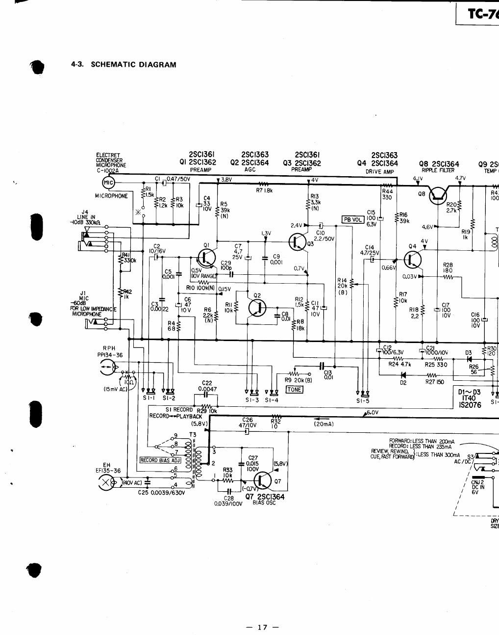
Sony tc 76 schematic

This is the 3 pages manual for sony tc 76 schematic.
Read or download the pdf for free. If you want to contribute, please mail your pdfs to info@audioservicemanuals.com.

Page: 1 / 3
left right
sony tc 76 schematic

Extracted text from sony tc 76 schematic (Ocr-read)


Page 2

TC 6 TC 76

09 ZSC|364 05,6 250383
TEMP COMP my; AMP
v 6.3V
my
R43
IOO $21k
cm
ms
5??? -l
m n ' 05 T2 .12
W MONlTOR
6mg fiafilfiréfiéfim
0-5" 5 .. $14" LOAD orlomoa
6 em R3! MORE
l20
-ll _
0°35
. sp
SPEAKER
CIS an
|00 9 «34:: mm
lOV my 2.2:: 2.2
52 men
omstmo
930 ME (FORWARD. )
ns <>l20 REC, - 39k FAST FORWARD
OCN.
3 SW?
5109
5mm

MOTOR D
D- 009G?)

m-nm mammal;
SlZE"D"4pcs 3mm
BP-BH

Note:

0 All capacitors are in uF unless otherwise noted. 50 or
less working volts are omitted except for elactrolytic type.
p-MuF

0 All resistors are in n. 34W, unless otherwise noted.
k = 1,000 M ' 1,000k

D In using electret condenser microphone with red mark
on side of ease, connect resistor R1 shown with A} in
parallel with H2.

0 (N) indiutesa low-noise resistor.

0 Voltages are DC with respect to ground unless otherwise
noted. Readings taken under no-signal conditions with a
VOM l20kan). Readings in ( lure in RECORD mode.
Voltage variations may be noted due to normal
production tolerances,

0 AC voltage readings on bias oscillator circuit taken with e
VTVM.

o - : 8+ circuit

0 Switch Mode:

Ref. No. Snitch Mode
51 RECORD/playback PLAVBACK
52 power OFF
83 ACIDC DC
84 START/STOP START
SS Voltage Selector
E _Mg)EL _
I .__4_| _
POWER
I N 1RANSFORMER F 00"
ll 05 cm»
" AC

/

_____ _.I

@366

IOO~||0V ll5~l27V$5

_18_

200* 220V 230~250V