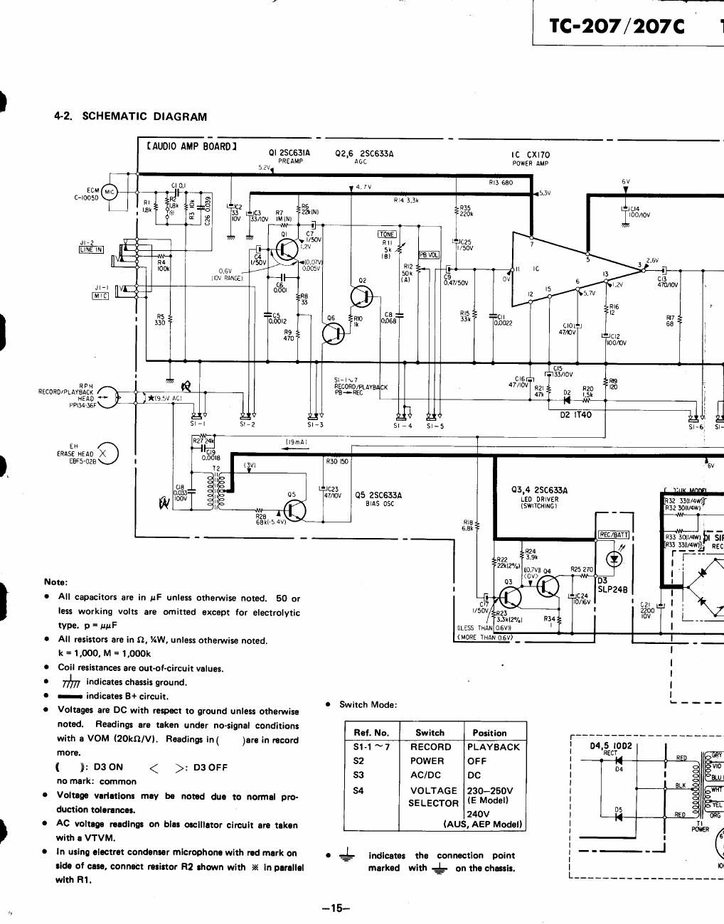
Sony tc 207 schematic

This is the 2 pages manual for sony tc 207 schematic.
Read or download the pdf for free. If you want to contribute, please mail your pdfs to info@audioservicemanuals.com.

Page: 1 / 2
left right
sony tc 207 schematic

Extracted text from sony tc 207 schematic (Ocr-read)


Page 1

4~2. SCHEMATIC DIAGRAM

[AUDIO AMP BEARD)

1c-2o7/207c ' 1

OI 25C63|fl 02,6 ZSCSBA IC CXITO
PREAMP AGC POWER AMP
52V
0 OJ 4 7] fill 650 6V
ecu i ' w V _
640050 a; x 3 RM 3.3x l
"' 13x 9 0. R6 R35 U4
l 3 x m 33 (3 n7 2mm 220x IOO/IOV
? k § Iov 331m IMiN) ,
0| c7
-2 36 ifszov
7 {of "
50 (OH/V
50% 05, u Jooccv -{ l }
HOV Rance! >--H- 02 354mm 0V gig/lav »
Jl-l _ ($0! RB
lfll < 33 ,
J- ms __
= CH _ --
' g?) acoglz .- °5 {10 ONT 33 053322 cm 237 1
R9 47/0v LJClZ ,
no lDOIlW
cls '
. s: I 7 mm FIBSIIOV m
. N .7
RN 7 Racono/mvsncx "0 RZI- n20 20 t
RECORDIPLAVEEAEE 93"? 7* E {5* l
H N r
PPlSd-ISSF 51;; id DZ 40 gig
Sl-l Sl»2 Slrd Sl~5 SFG Sl-
EH El (l9mfli
b..-
ERASE mo X m
Ears-028:) I 0.01:: 13v: R30 ISO lav
i
as j- 03 6 ZSCGSBA
10% 05 25C533A L'Eo DRIVER
W EIAS osc (swncumci
Rlfi .
6.8K
_ _ -
R24
3222 am
22ki2/.l mm 94 R25 270
(CV) W
Nora: I as Lg
C All capacitors are in uF unless omen/vise noted. 50 or 29"? Lng/ZISV
. . use»:
less working volts are ommed exnepi for electrolytic g3? R >
type. 9 - mnF ((LESS THAN osv» '
0 All resistors are in 9, AW, unless othemise noted, (MORE THAN 0'6-
k =1.000, M =1.000k
0 Coil resistances are out-of-circuK values. .
0 77%; indicates chassis ground.
a - indicates 8+ crcut.
' I . 0 Switch Mode:
0 Voliages are DC wuh respect to ground unlm Olhelwlta
. R - '
noted :dings are ni:n under no signal conditions a. No. Switch Pasition r ____________________
With a V0 (20an). endings In( )an in ncard Si-1~7 RECORD PLAYBACK : MIEECQODZ
more. D OFF 32 POWER OFF : 04 R vio
( )i: D3 0" < > 3 53 AC/DC DC : I am;
no mar : common LK
84 VOLTAGE 230-250V |
0 Voltage variations mcv be non-d duo to normal pro- SELECTOR (E Model) : y ,_
duction Iolorlnoas. 240V I D5 ORG
0 AC voltage wading: on blu oscillator circult are nknn lAUthEP Model) } pain 6
withIVTVM. : _ _i
. .L _ , , _ - _ -
o In using oiectm condenser microphone wlxh rod mark on . .- Indlcates the connection point I ,
_ I to

tide of m, connlcl minor H2 shown with ii£ In parallol
wlxh fii.

marked with g- on tho chassis.

-15-

Page 2

TC-207/207C

07/207c

5V

i L14
IIOO/IOV

LJCIZ
mom I

Non:

The power switch (82) sums ON in all modes
except for STOP and EJECT.

The motor-side switch turns ON firs: and then
the amplifier-side switch turns ON, and pre-
vent: click noise hearing from the speaker.
In STOP and EJECT modes, this switch turns
OFF in a reverse order.

w
,- - v- - -, -
FF an 5 a I: l 01 nggimo :
. In 0 1 LUGIN H
I :3, ( Powmcomlmo ma) : new m :
9132 Jul/4M; ¥ 7 a: INPUT SOCKET 1 I 240v .
$52301me - .
2 l °l I NJ
c 7 - : I I
RE CHARGEABLE: " Sfl'é-flfécgv I
I
_. BTW" ' , I_InzoIEc nmmmom : Us;
_ _ ' _ _ _ ELK wm _
., -' 1. av
| powsn
! UK MODEL
I L-
| l.
D1 SIREN)
: / i "L m I
| : .r l20V
I '
I I N
| l mu 1
I
I I . :
I I : A; new vm'r I
I |__._..._I 1: av I
I 5-..- POWER I
J |__ -_ USA MODEL l
L ______________________________________
04.5 I002 . ' I
RECT » I
_ R I
m
' I
ELK EL I
I
E RED I
" I
4 I
- . I \
-.._-_l ,, ' \
G i
l00~IKW II5~IZ1V 20th 230~250V I
_________ trauma sun: J . _

1"
.Iwfiy

--16-