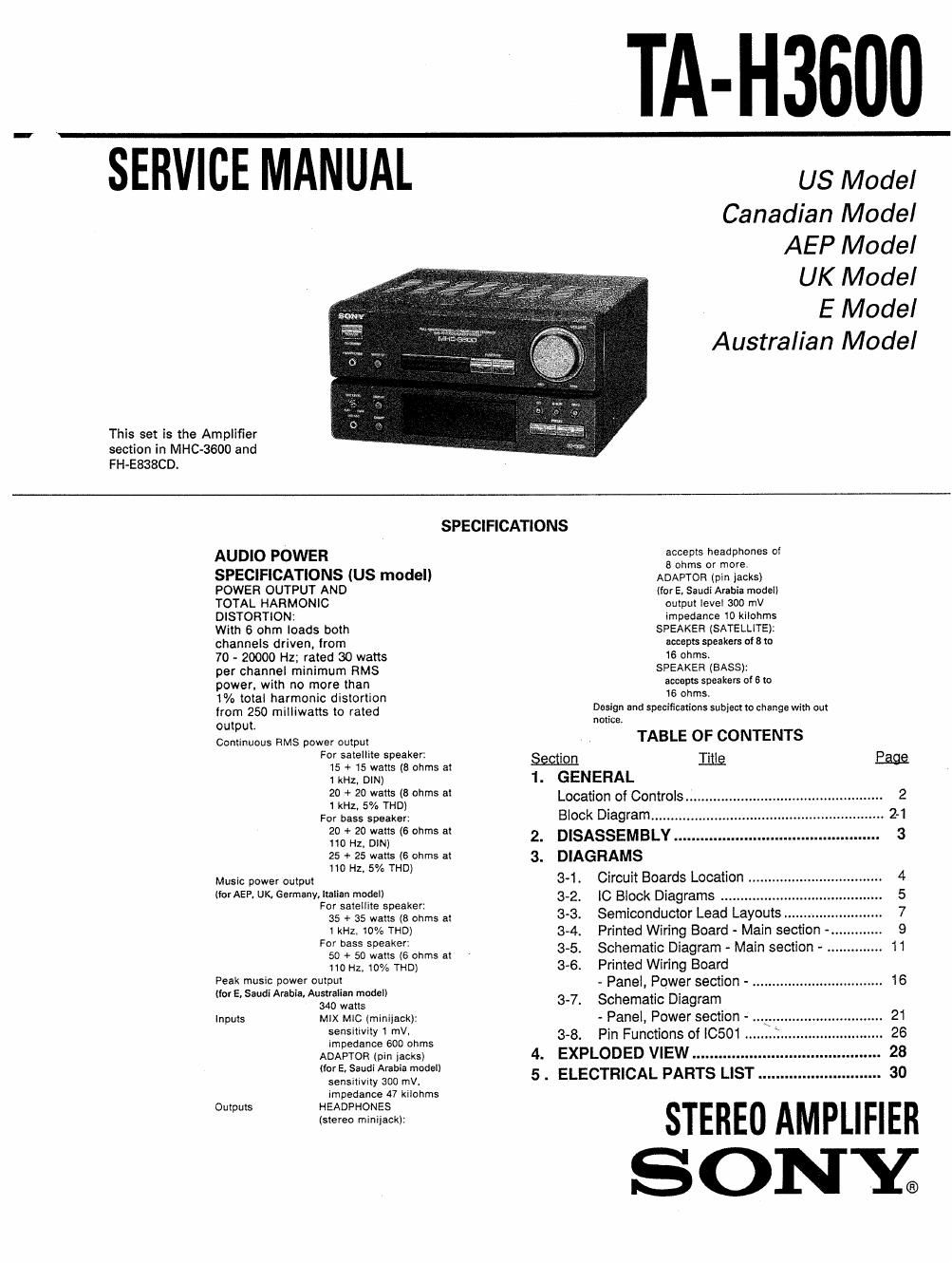
Sony ta h 3600 service manual

This is the 20 pages manual for sony ta h 3600 service manual.
Read or download the pdf for free. If you want to contribute, please mail your pdfs to info@audioservicemanuals.com.

Page: 1 / 20
left right
sony ta h 3600 service manual

Extracted text from sony ta h 3600 service manual (Ocr-read)


Page 1

TA-H3600

SERVICE MANUAL "'

US Model
Canadian Model
AEP Model

UK Model

E Model
Australian Model

This set is the Amplifier
section in MHC-SGOO and
FH-E838CD.

SPECIFICATIONS
AUD|O POWER accepts headphones cl
8 ohms or more.
SPECIFICATIONS (US model) ADAPTOR (pin jacks)
POWER OUTPUT AND (for E, Saudi Arabia model)
TOTAL HARMONlC output level 300 mV
DISTORTIONZ impedance 10 kilohms
With 6 ohm loads both SPEAKER (SATELLITE):
channels driven, from accepts speakers oI s to
70 - 20000 Hz; rated 30 watts 16 OhIrEnSIB
per channel minimum RMS SPEAK R Ass):
power, with no more than accepts speakers offito
1% total harmonic distortion . 16 Oljms- '
from 250 milliwatts to rated Design and specifications subiecr to change With out
OUIDUL notice,
Continuous RMS power output TABLE OF CONTENTS
For satellite speaker: ~
15 + 15 watts (8 ohms at m LILQ Raga
1 kHz. DlN) 1. GENERAL
20 + 20 watts (8 ohms at
1 km 5% mo) Location of Controls
For bass speaker: Block Diagram ........
20 + 20 watts (6 ohms at 2 DISASSEMBLY
110 Hz. 0m) .
25 + 25 walls (6 ohms at 3_ DIAGRAMS
110 Hz. 5% THD) . .
Music power output 3-1. CIrCUlI Boards Location
liorAEP, UK, Germany. ltalian model) 3_2 IC Block Diagrams
For satellite 5 eaker: ' , """
35 + 35 watt: (8 ohms at 3-3. Semiconductor Lead Layouts.
1 kHz. 10% THD) 3-4. Printed Wirin Board - Main section
For bass speaker t .g u .
50 + so "5 (5 0th at 3-5. Sohemane lDIagram - Main sectIon -
no Hz, 10% THD) 3-6. Printed WIrIng Board
:93: :"jFrbwfifuufulf d I) - Panel, Power section - ................. . ............... 16
(or , au I re In, S a non me e 37. Schematic Dia ram
340 watts
Inputs MIX Mic lminiiack): - Panel, Power section -
5 1 '"V' 3-8. Pin Functions of |0501 ..
Impedance 600 ohms
ADAPTOR lpln lacks) 4. EXPLODED VIEW
(for E, Saudi Arabia model)
sensitiviw 300 mv. 5 . ELECTRICAL PARTS LIST 30
impedance 47 kilohms
Outputs HEADPHONES

(stereo miniIack):

STEREO AMPLIFIER
SON E

Page 2

TA-H3600

SAFETY CHECK-OUT

After correcting the original service problem, perform the
following safety check before releasing the set to the customer:
Check the antenna terminals, metal trim, "metallized" knobs, screws,
and all other exposed metal parts for AC leakage. Check leakage as
described below.

LEAKAGE TEST

The AC leakage from any exposed metal part to earth ground
and from all exposed metal pans to any exposed metal part having
a return to chassis, must not exceed 0.5mA (500 microampers).
Leakage current can be measured by any one of three methods.

1. A commercial leakage tester, such as the Simpson 229 or RCA
WT-540A. Follow the manufacturers' instructions to use these
instruments.

2. A battery-operated AC milliammeterl The Data Precision 245
digital multimeter is suitable for this job.

SAFETY»RELATED COMPONENT WARNING] I

COMPONENTS IDENTIFIED BY MARK A OR DOTTED LINE
WITH MARK A ON THE SCHEMATIC DIAGRAMS AND IN
THE PARTS LIST ARE CRITICAL TO SAFE OPERATION. REPLACE
THESE COMPONENTS WITH SONY PARTS WHOSE PART
NUMBERS APPEAR AS SHOWN IN THIS MANUAL OR IN
SUPPLEMENTS PUBLISHED BY SONY.

3. Measuring the voltage drop across a resistor by means of a
VOM or battery-operated AC voltmeter. The "limit" indica-
tion is 0.75V, so analog meters must have an accurate low-
voltage scale. The Simpson 250 and Sanwa SH-63Trd are
examples of a passive VOM that is suitable. Nearly all battery
operated digital multimeters that have a 2V AC range are
suitable. (See Fig.A)

To Exposed Metal
Parts on Set

' Ac
-15) / voltmeter

0.15m:
. (0.75M
._l

7" Earth Ground
Fig. A. Using an AC voltmeter to check AC leakage.

ATTENTION AU COMPOSANT AYANT RAPPORT
A LA SECURITEI

LES COMPOSANTS IDENTIFIES PAR UNE MARQUE A SUR
LES DIAGRAMMES SCHEMATIOUES ET LA LISTE DES PIECES
SONT CRITIQUES POUR LA SECURITE DE FONCTIONNE-
MENT. NE REMPLACER SES COMPOSANTS QUE PAR DES
PlECES SONY DONT LES NUMEROS SONT DONNES DANS
CE MANUEL 0U DANS LES SUPPLEMENTS PUBLIES PAR
SONY.

SECTION 1
GENERAL
LOCATION OF CONTROLS This section is extracted from
El SYSTEM POWER switch and STANDBY instruction manual.
Indicator

The indicator remains lit as long as the
AC power cord is connected to a wall
outlet.

E] HEADPHONES iack (stereo minijack)

WAKE UP button and indicator

MIC (microphone) LEVEL control

[3 MIX MIC (microphone) input jack

IE DISPLAY button

DIRECT button

Function indication display

[3] FUNCTION <> buttons

VOLUME control

EQ (equalizer) button and indicator

(El S indicator

DBFB (Dynamic Bass Feedback) button
and indicator

PRESET buttons

[E] Display window